
Eureka
For R&D, Eureka makes reading and utilizing patents & technical documents easy.
Eureka AIR
Designed for self-driven R&D workflows. Generate viable solutions, solve complex R&D challenges, empower your innovation with AI.

Eureka Materials
Designed for material experts only. Revolutionize your material R&D, from search, analyze, to developing new materials.

TechResearch
Generate reliable direction feasibility study reports for your R&D in just a few steps.

TechSeek
Discover and master advanced knowledge NOW. Basics, ideas, possibilities, all at once.

TechMind
As an expert in R&D Theories, TechMind can generates customized viable solutions instantly.

TechRisk
Analyze your overall solution with one click, know your potential R&D risks in advance.

TechMonitor
Get weekly tech updates, stay abreast of the latest tech innovations and key insights.
Double-door structure capable of preventing door from slightly rotating
A micro-rotation, double-door technology, used in special equipment for doors/windows, windows/doors, building components, etc., can solve problems such as device function damage, poor door sealing, and damage to refrigerator storage functions.
- Summary
- Abstract
- Description
- Claims
- Application Information
AI Technical Summary
Problems solved by technology
Method used
Image

Examples
Embodiment 1
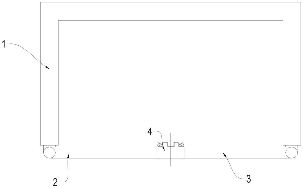
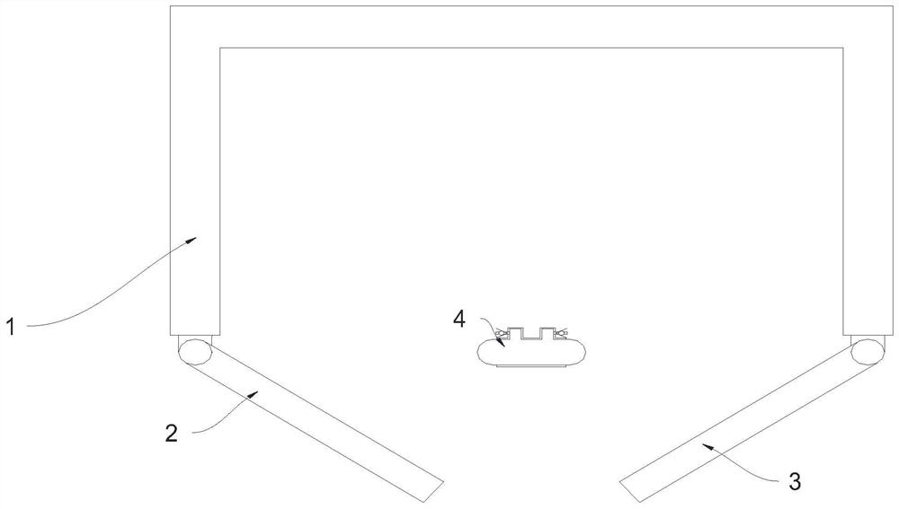
[0026] Example 1: See Figure 1-5 A double door structure that prevents the door from turning slightly, it includes a box body 1, a first door 2, a second door 3 and an airbag structure 4, a box body 1, a first door 2, a second door 3 and an airbag structure 4 enclosing an inner cavity, the first door 2 is rotatably connected to the left side wall of the box body 1, the second door 3 is rotatably connected to the right side wall of the box body 1, and the airbag structure 4 is arranged on the first door 2 and the second door 3 Between, the upper end of the air bag structure 4 is connected with the inner top wall of the box body 1, the lower end of the air bag structure 4 is connected with the inner bottom wall of the box body 1, and the air bag structure 4 initially has gas inside, which is used to ensure that when one door is closed, the other When a door is closed, the tightness of the closed door.
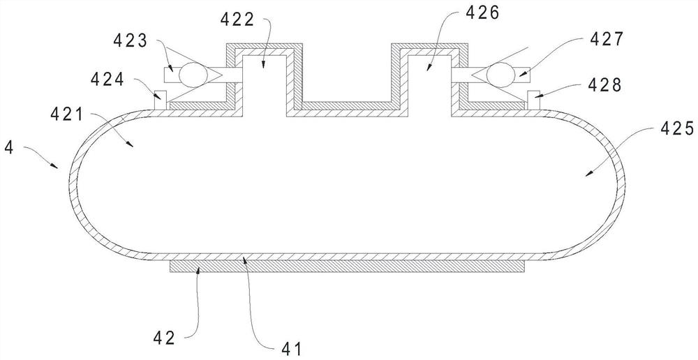
[0027] The airbag structure 4 includes an installation layer 41 and an air...
Embodiment 2
[0037] Embodiment 2: Different from Embodiment 1, the lower end of the airbag structure 4 is rotatably connected to the inner lower end of the box body 1, and the upper end of the airbag structure 4 is detachably connected to the inner top end of the box body 1. It is a kind of prior art, which can facilitate the disassembly of a section of the airbag solution structure 4, and is convenient for storing and taking larger things.
Embodiment 3
[0038] Embodiment 3: see Figure 6 , when different from Embodiment 1, a fourth one-way valve 5 may be provided on the side wall of the box body 1. When the door is closed, when the inner cavity pressure formed between the box body 1 and the door increases, the The fourth one-way valve 5 discharges part of the gas, so that the gas pressure in the inner cavity tends to be stable, which facilitates the closing of the door.
PUM
 Abstract
Description
Claims
Application Information
 - R&D Engineer
- R&D Manager
- IP Professional
- Industry Leading Data Capabilities
- Powerful AI technology
- Patent DNA Extraction
Browse by: Latest US Patents, China's latest patents, Technical Efficacy Thesaurus, Application Domain, Technology Topic, Popular Technical Reports.
© 2024 PatSnap. All rights reserved.Legal|Privacy policy|Modern Slavery Act Transparency Statement|Sitemap|About US| Contact US: help@patsnap.com