Supercharge Your Innovation With Domain-Expert AI Agents!

A light guide performance detection device applied to an LED light guide plate

A detection device and light guide plate technology, which is applied in the direction of measuring device, optical performance test, optical instrument test, etc., can solve problems such as the inability to measure the light guide performance of the LED light guide plate, the inability to detect, and the inability to drive the LED light guide plate to adjust.

Active Publication Date: 2021-10-12
深圳市日昌晶智能光电有限公司
View PDF7 Cites 0 Cited by
  • Summary
  • Abstract
  • Description
  • Claims
  • Application Information

AI Technical Summary

Problems solved by technology

[0005] In order to solve the above technical problems, the present invention provides a light guide performance detection device applied to LED light guide plates, to solve the problem that when the existing light guide performance detection devices of LED light guide plates are in use, the detection is usually performed in a place with bright light. , the detection accuracy is reduced, it is impossible to perform convenient detection in a dark environment, it is impossible to detect the LED light guide plate in an environment with different brightness, it is impossible to detect the upper and lower ends of the LED light guide plate in different brightness environments, and it is impossible to detect when the light guide plate is in a different brightness environment. Adjust the brightness inside the device, and when the existing light guide performance detection device of the LED light guide plate is in use, it cannot measure the light guide performance of the LED light guide plate at different positions from the light source, cannot drive the LED light guide plate to adjust for detection, and cannot test the LED light guide plate. The problem of automatic strengthening and fixing when the light guide plate is adjusted and detected

Method used


Image

  • A light guide performance detection device applied to an LED light guide plate
  • A light guide performance detection device applied to an LED light guide plate
  • A light guide performance detection device applied to an LED light guide plate

Examples


Embodiment

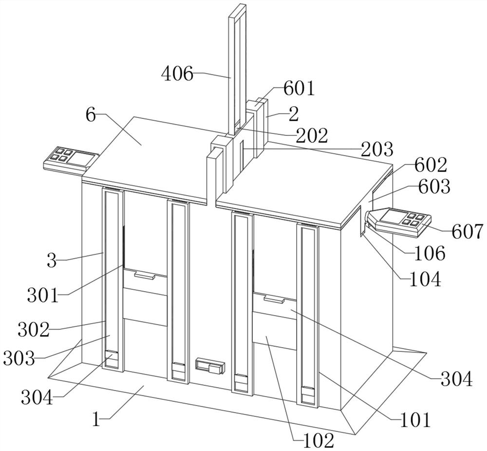
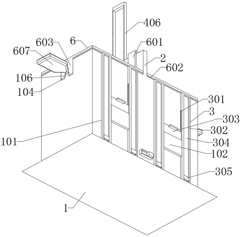
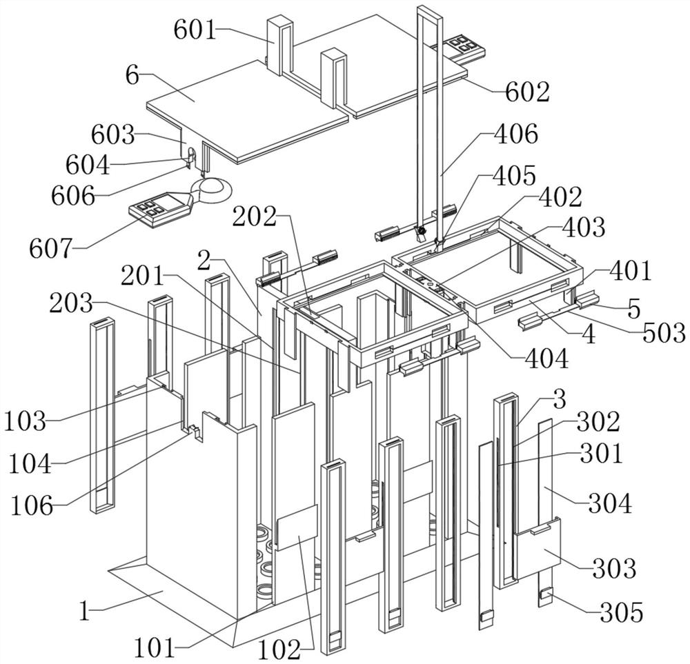
[0082] as attached figure 1 To attach Figure 11 Shown:

[0083] The invention provides a light guide performance detection device applied to LED light guide plates, which includes a main body 1; A spotlight is installed at the bottom, and a partition 2 is fixedly installed in the middle of the main body 1. Eight mounting parts 3 are installed on both sides of the main body 1 through side grooves 101. The top of the main body 1 is covered with a top plate 6; the partition 2, The partition 2 is a T-shaped structure, and the partition 2 is made of metal, and the middle groove 203 of the partition 2 is embedded with a slider 403 for installing the moving part 4; the installation part 3 is a rectangular strip structure, and the installation The part 3 is made of rubber; the moving part 4, the moving part 4 also includes a control mechanism, and the control mechanism is installed inside the stress groove 404 of the moving part 4. The moving part 4 is composed of two rectangular f...


PUM


Abstract

The invention provides a light guide performance detection device applied to LED light guide plates, which relates to the field of light guide detection, to solve the problem that the existing light guide performance detection devices of LED light guide plates cannot measure the different positions of the light guide plate from the light source when in use The light guide performance of the LED light guide plate cannot be driven to adjust for detection, including the main body; the main body is a rectangular structure, and the outside of the bottom of the main body is an inclined structure, the inside of the main body is a rectangular structure, and the inner bottom of the main body is installed. For spotlights, a partition is fixedly installed in the middle of the main body. Two LED light guide plates are embedded inside the moving part, so that they can form a contrast during detection. By manually controlling the lever to move downward, the moving part can drive the LED light guide plate into the interior of the main body, and control the luminance meter to test the LED light guide plate. The light guide brightness at the current distance, by quickly pulling the lever and then pressing it, the moving part can drive the LED light guide plate at different distances to measure the light guide through the luminance meter.

Description

technical field [0001] The invention belongs to the technical field of light guide detection, and more specifically relates to a light guide performance detection device applied to an LED light guide plate. Background technique [0002] During the production process of the LED light guide plate, random inspection and sampling are usually required, and a light guide performance detection device is required during the inspection to detect the light guide performance of the LED light guide plate and whether the LED light guide plate is qualified. [0003] For example, the application number: CN201510383987.4 relates to a light guide plate detection device, which includes a mounting base, a detection platform, a side light source device, a camera bracket, and a camera. The upper surface of the mounting base is connected to a fixed detection platform, a side light source device, and a camera bracket. A fixed camera is connected to the camera bracket, and the detection platform in...

Claims


Application Information

Patent Timeline
Patent Type & Authority Patents(China)
IPC IPC(8): G01M11/02
CPCG01M11/0207G01M11/0214
Inventor 陆涌
Owner 深圳市日昌晶智能光电有限公司
Features
  • R&D
  • Intellectual Property
  • Life Sciences
  • Materials
  • Tech Scout
  • Unparalleled Data Quality
  • Higher Quality Content
  • 60% Fewer Hallucinations
Learn More