
Pixel driving circuit and driving method thereof, and display panel

A technology of pixel driving circuit and driving sub-circuit, which is applied to static indicators, digital memory information, instruments, etc., can solve the problems of display panel display effect, high luminous power consumption, and reduced luminous efficiency.

Active Publication Date: 2022-08-09
BOE TECH GRP CO LTD
View PDF5 Cites 0 Cited by
  • Summary
  • Abstract
  • Description
  • Claims
  • Application Information

AI Technical Summary

Problems solved by technology

However, due to the uniformity of the manufacturing process, the turn-on voltage of the micro-light-emitting device will be inconsistent, and the photoelectric conversion characteristics (including photoelectric conversion efficiency, uniformity, and color coordinates, etc.) of the micro-light-emitting device will vary with the current flowing. For example, at low current density, the luminous efficiency of micro-light emitting devices will decrease with the decrease of current density, resulting in high luminous power consumption. When it is applied to the display panel, it will affect the display effect of the display panel. cause a certain impact

Method used


Image

  • Pixel driving circuit and driving method thereof, and display panel
  • Pixel driving circuit and driving method thereof, and display panel
  • Pixel driving circuit and driving method thereof, and display panel

Examples


Embodiment Construction

[0037] The technical solutions in the embodiments of the present invention will be clearly and completely described below with reference to the accompanying drawings in the embodiments of the present invention. Obviously, the described embodiments are only a part of the embodiments of the present invention, rather than all the embodiments. Based on the embodiments of the present invention, all other embodiments obtained by those of ordinary skill in the art without creative efforts shall fall within the protection scope of the present invention.

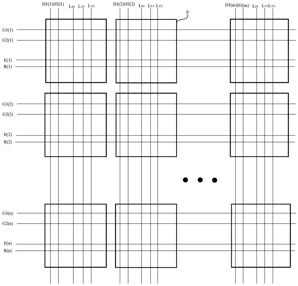
[0038] Embodiments of the present invention provide a display device including a display panel. like figure 1 As shown, the display panel includes a plurality of sub-pixels P.

[0039] It should be noted, figure 1 The above-mentioned plurality of sub-pixels P are arranged in an array of n rows and m columns as an example for illustration, but the embodiment of the present invention is not limited to this, and the above-mentioned pl...


PUM


Abstract

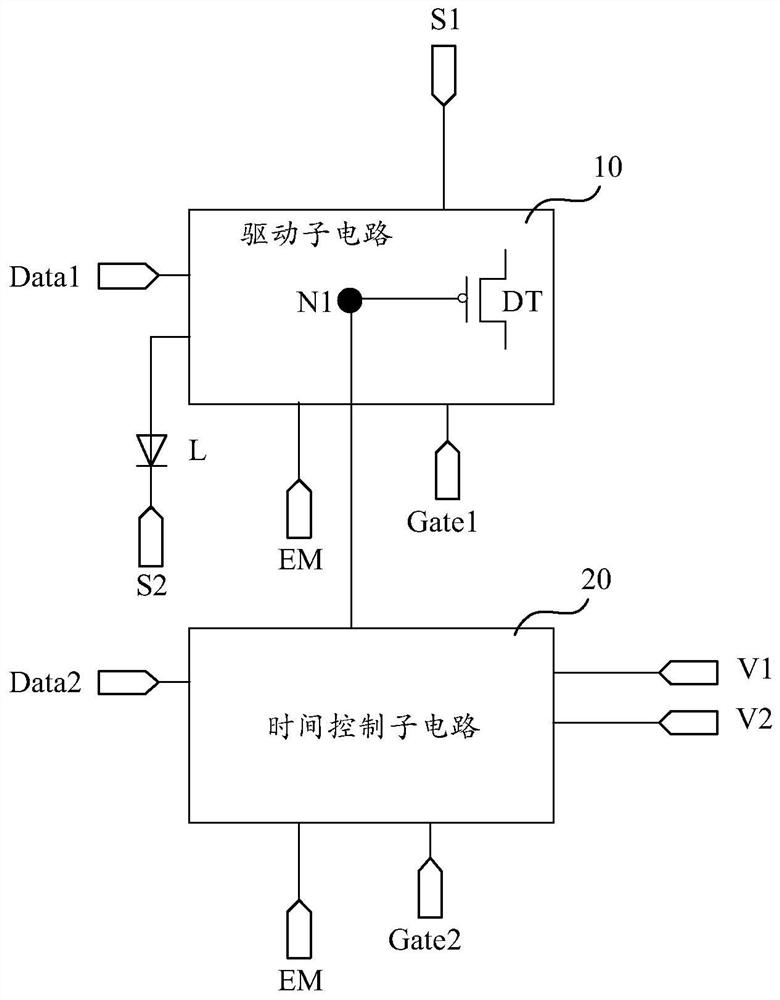
Embodiments of the present invention provide a pixel driving circuit, a driving method thereof, and a display panel, which relate to the field of display technology and can improve the display effect of the display panel. A pixel driving circuit, comprising: a driving sub-circuit provides a driving signal to a to-be-driven element under the control of a first scanning signal terminal and an enabling signal terminal; the driving signal and the signals of the first data signal terminal and the first power supply voltage signal terminal Relevant; under the control of the second scan signal terminal, the time control sub-circuit writes the signal of the second data signal terminal and the second voltage signal terminal, and under the control of the enable signal terminal, writes the signal of the first voltage signal terminal, and writes the signal of the first voltage signal terminal to the first voltage signal terminal. The signals of the two voltage signal terminals are transmitted to the first node, the driving transistor is turned off, and the working duration of the to-be-driven element is controlled; the working duration of the to-be-driven element is related to the signals of the second data signal terminal and the first voltage signal terminal.

Description

technical field [0001] The present invention relates to the field of display technology, and in particular, to a pixel driving circuit and a driving method thereof, and a display panel. Background technique [0002] Self-luminous devices have attracted extensive attention due to their high brightness and wide color gamut. However, its transfer binding technology is immature, and there is no corresponding glass-based driver backplane, which is limited when it is introduced to the consumer market. [0003] The size of the pixel driving circuit composed of micro light-emitting devices is relatively small, which can be applied to the glass-based driving backplane. However, due to the uniformity of the manufacturing process, the turn-on voltage of the micro light-emitting device will be inconsistent, and the photoelectric conversion characteristics (including photoelectric conversion efficiency, uniformity and color coordinates, etc.) of the micro light-emitting device will chan...

Claims


Application Information

Patent Timeline
Patent Type & Authority Patents(China)
IPC IPC(8): G09G3/32G09G3/3208
CPCG09G3/32G09G3/3208G09G3/3266G09G2310/0286G11C19/28G09G2330/021G09G3/3233G09G2300/0819G09G2300/0842G09G2300/0861G09G2300/0426G09G2300/0809G09G2310/061G09G2310/08G09G2320/0233
Inventor 玄明花刘冬妮齐琪刘静岳晗
Owner BOE TECH GRP CO LTD
Learn More