Self-locking bracket and orthodontic appliance

A self-locking bracket and self-locking technology, applied in the field of orthodontics, can solve problems such as low manufacturing precision, increased friction, and difficult operation, and achieve the effects of simple and reliable structure, stable self-locking performance, and convenient operation

Pending Publication Date: 2021-07-09
GUANGZHOU RITON BIOMATERIAL
View PDF0 Cites 0 Cited by
  • Summary
  • Abstract
  • Description
  • Claims
  • Application Information

AI Technical Summary

Problems solved by technology

In the prior art, elastic ligature rings or ligature wires are usually used to bind the archwire around the ligature wing to complete the fixation of the archwire. This method tends to increase the friction between the bracket and the archwire, and the corresponding The speed of tooth movement will become smaller, resulting in a longer treatment cycle
In addition, during the treatment process, the arch wire needs to be replaced regularly according to the progress of the treatment. Every time the arch wire is replaced, the ligature ring or ligature wire needs to be removed, which increases the operation of medical staff and virtually increases the treatment time, which is not conducive to improving the treatment efficiency.
[0003] Of course, in order to improve the efficiency of correction, there are some self-locking brackets that do not require ligature rings or ligature wires in the prior art, but the structure of these self-locking brackets has unreasonable switch lock structure, complex structure, difficult operation, and difficult cleaning. , high manufacturing difficulty, low manufacturing precision and other issues, need to be further optimized

Method used


Image

  • Self-locking bracket and orthodontic appliance
  • Self-locking bracket and orthodontic appliance
  • Self-locking bracket and orthodontic appliance

Examples


Embodiment Construction

[0028] The specific implementation manners of the present invention will be further described in detail below in conjunction with the accompanying drawings and embodiments. The following examples are used to illustrate the present invention, but are not intended to limit the scope of the present invention.

[0029] It should be understood that the terms "front", "rear" and the like are used in the present invention to describe various information, but the information should not be limited to these terms, and these terms are only used to distinguish the same type of information from each other. For example, "before" information could also be called "after" information, and "after" information could also be called "before" information without departing from the scope of the present invention.

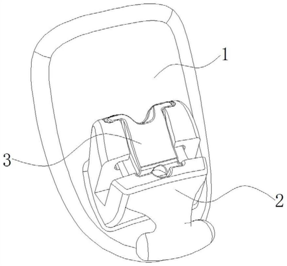
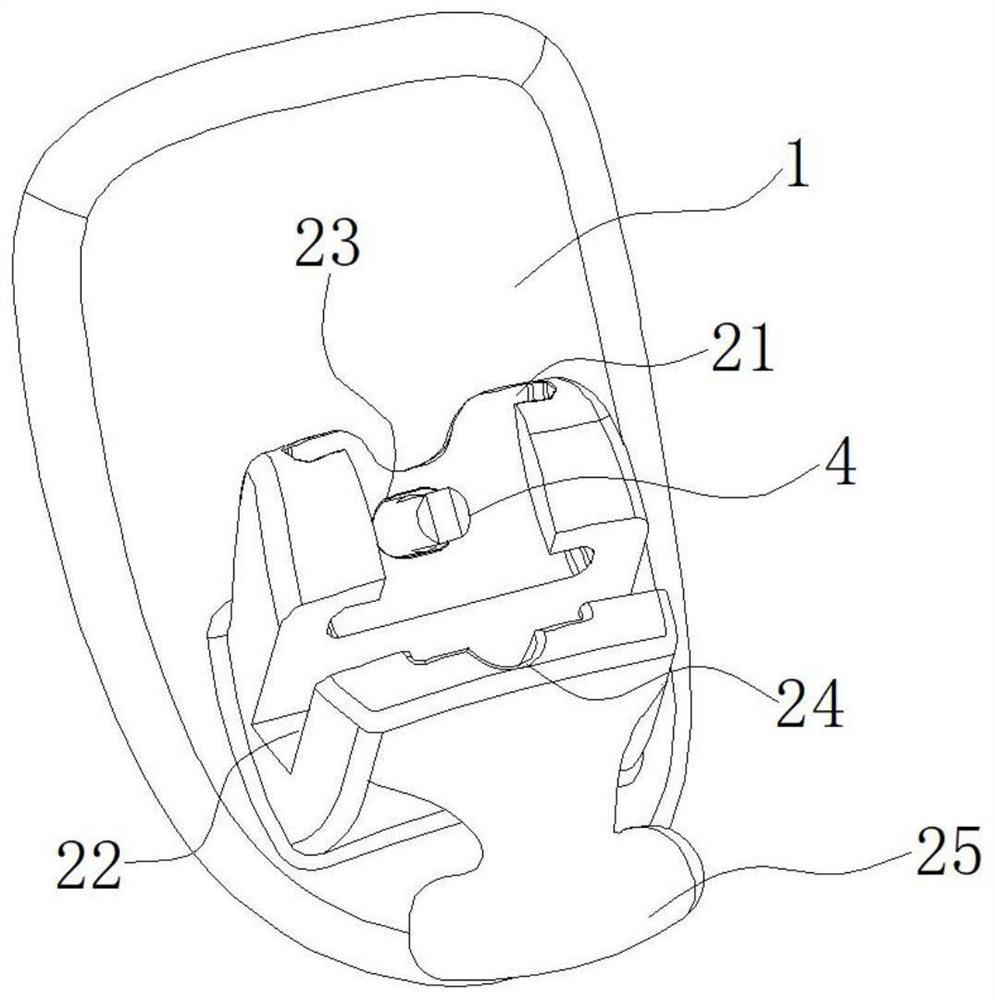
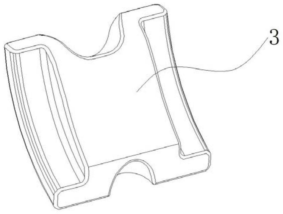
[0030] Such as Figure 1 to Figure 8 As shown, the embodiment of the present invention provides a self-locking bracket of a tooth aligner, specifically, it includes a bottom plate 1, a b...


PUM


Abstract

The invention relates to the technical field of orthodontics, and discloses a self-locking bracket. The self-locking bracket comprises a bottom plate, a bracket body, a self-locking cover and a lock cylinder, wherein the bottom plate is used for being connected to the lip side face or the tongue side face of a tooth; the bracket body is connected to the side face, back to the tooth, of the bottom plate; a groove used for containing an arch wire is formed in the bracket body; the self-locking cover is arranged on the bracket body and used for covering the groove; a sliding groove is formed in the side, facing the bracket body, of the self-locking cover; the lock cylinder is made of an elastic material and comprises a fixed section fixedly connected with the bracket body and a deformation section arranged in the sliding groove; and the middle of the deformation section is hollowed out and forms a gap. The self-locking bracket provided by the invention is simple and reliable in structure, convenient to operate and easy to clean, the self-locking cover does not shake during use, and self-locking performance is stable. The invention also provides an orthodontic appliance which adopts the self-locking bracket. Thus, the orthodontic appliance also has the advantages of simple and reliable structure, convenience in operation, easiness in cleaning, stable self-locking performance and the like.

Description

technical field [0001] The invention relates to the technical field of orthodontics, in particular to a self-locking bracket and an orthodontic device. Background technique [0002] Fixed orthodontic treatment is one of the most common methods in orthodontic treatment. It is mainly completed by bracket aligners. In actual operation, the brackets are bonded to the surface of the patient's teeth and matched with the fixed archwires set in the bracket grooves. The orthodontic force is generated by the deformation of the arch wire, and then the teeth are arranged and moved to achieve the purpose of orthodontics. In the prior art, elastic ligature rings or ligature wires are usually used to bind the archwire around the ligature wing to complete the fixation of the archwire. This method tends to increase the friction between the bracket and the archwire, and the corresponding The speed of tooth movement will be reduced, resulting in a longer treatment cycle. In addition, during ...

Claims


Application Information

Patent Timeline
Patent Type & Authority Applications(China)
IPC IPC(8): A61C7/34A61C7/08
CPCA61C7/08A61C7/34
Inventor 李祖安赖奕潮王红卫程留青
Owner GUANGZHOU RITON BIOMATERIAL
Why Eureka
Try Eureka