Support frame for bridge detection
A bridge detection and support frame technology, applied in bridges, bridge parts, bridge construction and other directions, can solve the problems of fixed length of the support frame, unable to adjust the length of the support frame freely, unable to control the automatic movement of the support frame, etc. The effect of improving stability
- Summary
- Abstract
- Description
- Claims
- Application Information
AI Technical Summary
Problems solved by technology
Method used
Image
Examples
Embodiment 1
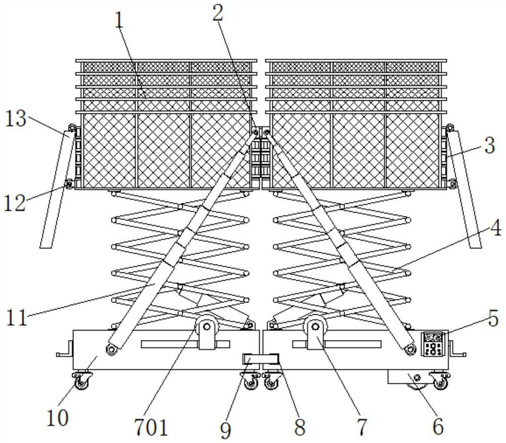
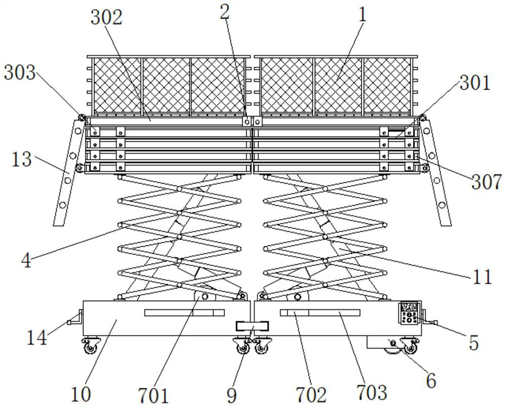
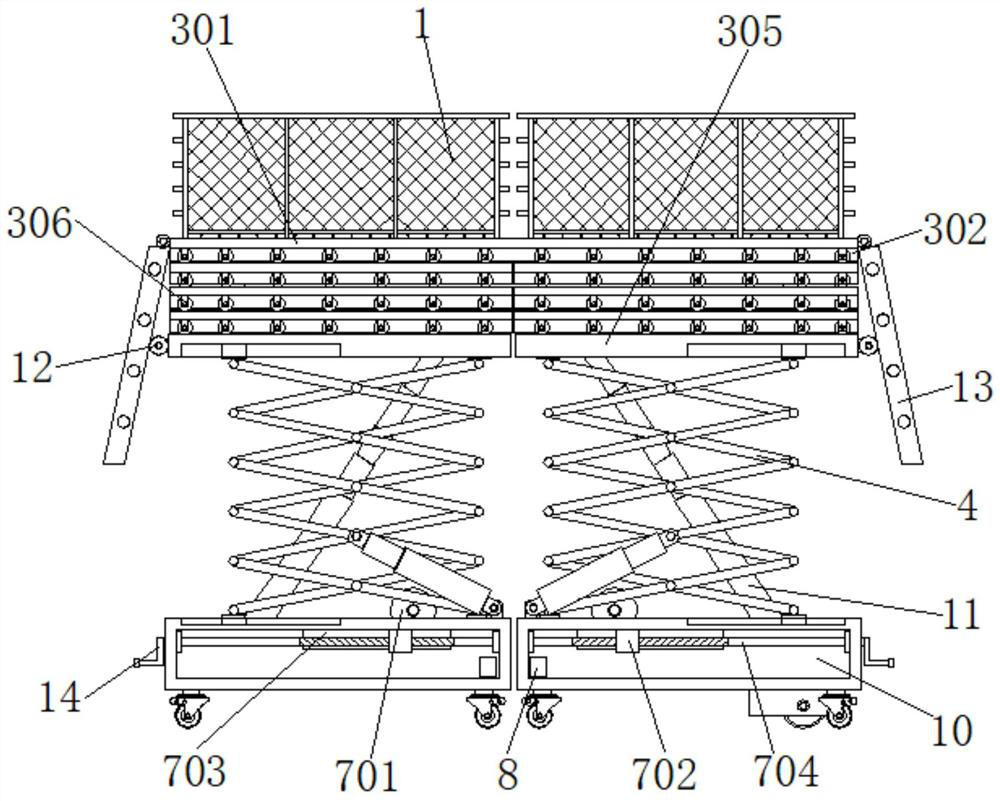
[0031] Example 1, such as figure 1 , 2 , 3, 4 and 6, when it is necessary to control the elongation of the entire support frame, the two sets of U-shaped latches 9 connected together on the two sets of installation warehouses 10 are pulled out from the inside of the slot 8, and then the control panel 5 is used to control the hydraulic expansion Rod 601 is extended until drive wheel 603 touches the ground. Then the driving motor 604 is controlled to drive the driving wheel 603 to move slowly, so that the set of installation bins 10 gradually moves away from the other set of installation bins 10 , and the limit pulley 304 rolls on the inner side of the limit chute 302 during the process. After four sets of limit pulleys 304 at the bottom moved to the anti-off block 307 at one end of the corresponding limit chute 302, the four sets of limit pulleys 304 on the upper floor continued to roll on the inside of the corresponding limit chute 302, and the multiple sets of stand plates 3...
Embodiment 2
[0032] Example 2, such as Figure 1-6 As shown, after the support frame is extended to both ends, the telescopic rod 11 is gradually elongated, and the inclination angle of the telescopic rod 11 is also gradually reduced. Then by turning the L-shaped handle 14, the guide wheel 701 is forced to move to the bottom of the outside of the telescopic rod 11, and the internal thread block 702 is forced to gradually move to the end close to the L-shaped handle 14 until the bottom of the outside of the telescopic rod 11 is firmly locked in. The inner side of the guide wheel 701. Utilize the guide wheel 701 to resist the telescopic rod 11, and limit the angle between the telescopic rod 11 and the top plane of the installation chamber 10 to be unable to continue to be smaller, so that the position of the telescopic rod 11 is restricted, thereby using the telescopic rod 11 as a telescopic plate The component 3 provides a stable support force, which ensures the stability of the entire sup...
PUM
 Abstract
Description
Claims
Application Information
 - R&D
- Intellectual Property
- Life Sciences
- Materials
- Tech Scout
- Unparalleled Data Quality
- Higher Quality Content
- 60% Fewer Hallucinations
Browse by: Latest US Patents, China's latest patents, Technical Efficacy Thesaurus, Application Domain, Technology Topic, Popular Technical Reports.
© 2025 PatSnap. All rights reserved.Legal|Privacy policy|Modern Slavery Act Transparency Statement|Sitemap|About US| Contact US: help@patsnap.com


