A Quasi-zero Stiffness Absolute Displacement Sensor Based on Electromagnetic Positive Stiffness

A displacement sensor, quasi-zero stiffness technology, applied in the direction of using electromagnetic means, instruments, electrical devices, etc., can solve the problems of lack of measurement objects, unachievable time response, affecting measurement accuracy, etc., to eliminate nonlinear effects, The effect of reducing the overall stiffness and reducing the volume of the mechanism

Active Publication Date: 2022-04-29
CHONGQING UNIV
View PDF4 Cites 0 Cited by
  • Summary
  • Abstract
  • Description
  • Claims
  • Application Information

AI Technical Summary

Problems solved by technology

However, many times the measurement object does not have an absolutely static reference point, and the absolute displacement of the system cannot be directly measured
Indirect measurement often brings errors and time delays. Some system controls with relatively high precision requirements and relatively short time response cannot achieve good control results because they cannot directly measure the absolute displacement of the system. Although some existing advanced measurement technologies can Applied to the measurement of absolute displacement (such as inertial sensors, radar or laser technology, etc.), but these measurement technologies have problems such as low precision, poor real-time performance, and high cost, and cannot be used in occasions with harsh working conditions; traditional quasi-zero stiffness based on electromagnetic The absolute displacement sensor uses a mechanical spring as a positive stiffness mechanism. At ultra-low frequencies, its damping cannot be ignored, which affects the measurement accuracy

Method used


Image

  • A Quasi-zero Stiffness Absolute Displacement Sensor Based on Electromagnetic Positive Stiffness
  • A Quasi-zero Stiffness Absolute Displacement Sensor Based on Electromagnetic Positive Stiffness
  • A Quasi-zero Stiffness Absolute Displacement Sensor Based on Electromagnetic Positive Stiffness

Examples


Embodiment Construction

[0055] The following will clearly and completely describe the technical solutions in the embodiments of the present invention with reference to the accompanying drawings in the embodiments of the present invention. Obviously, the described embodiments are only some, not all, embodiments of the present invention. Based on the embodiments of the present invention, all other embodiments obtained by persons of ordinary skill in the art without making creative efforts belong to the protection scope of the present invention.

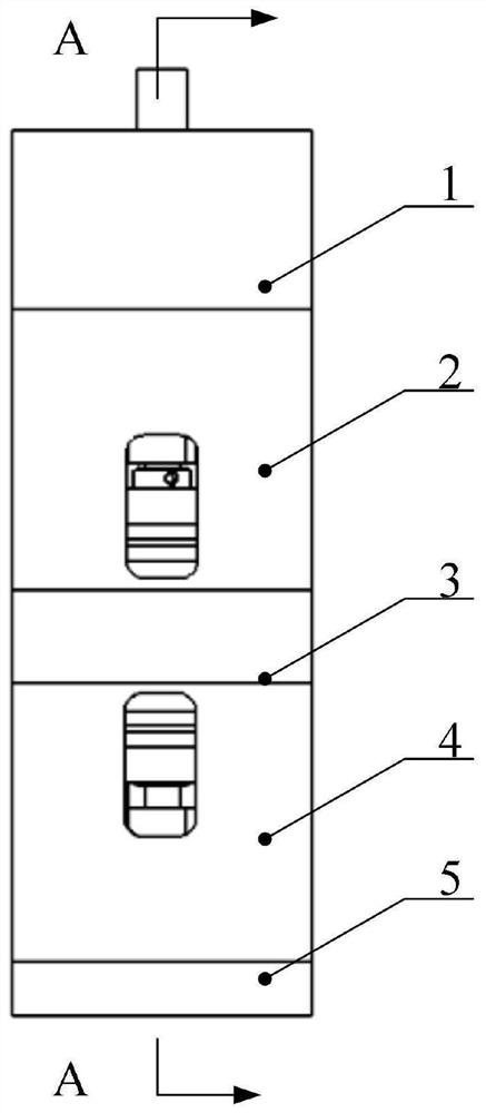
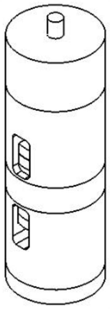
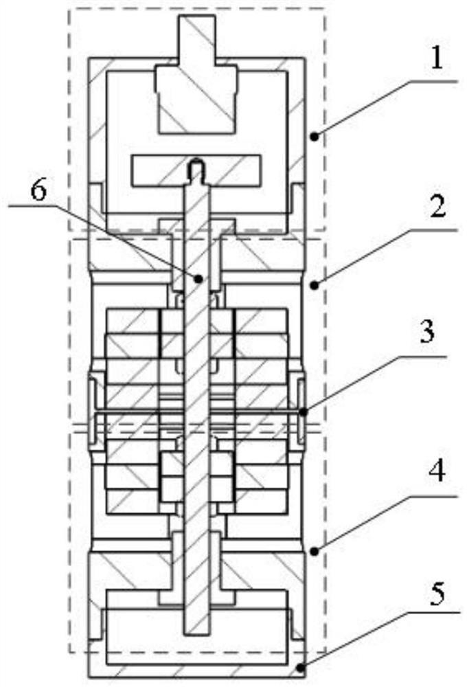
[0056] Such as Figures 1 to 21 As shown, this embodiment provides a quasi-zero stiffness absolute displacement sensor based on electromagnetic positive stiffness, including an eddy current displacement sensor unit, a negative stiffness unit, an intermediate connecting body, a positive stiffness unit, and a bottom shell sequentially connected from top to bottom ; Also includes a movement shaft that runs through the negative stiffness unit, the intermediate con...


PUM


Abstract

The invention discloses a quasi-zero stiffness absolute displacement sensor based on electromagnetic positive stiffness, relates to the technical field of vibration measurement, and comprises an eddy current displacement sensor unit, a negative stiffness unit, an intermediate connecting body, a positive stiffness unit, a bottom shell and a motion shaft. It can effectively reduce the damping of the mechanism, improve the service life of the system, and reduce the volume of the mechanism. By adjusting the number of layers of permanent magnets and coils in the electromagnetic positive stiffness unit and negative stiffness unit and controlling the magnitude of the current in the coil, the electromagnetic force between the permanent magnet and the electromagnetic coil can be changed, and the positive stiffness and negative stiffness can be adjusted to realize the whole Control of system stiffness. The positive stiffness and negative stiffness are approximately linear within a certain range, which can eliminate the influence of nonlinearity. After the positive and negative stiffness are superimposed, the overall stiffness of the system can be minimized, quasi-zero stiffness can be achieved, and higher measurement accuracy can be obtained. Selecting the initial position and motion range of the permanent magnet can make the system reach a quasi-zero stiffness state with a certain load capacity.

Description

technical field [0001] The invention relates to the technical field of vibration measurement, in particular to a quasi-zero stiffness absolute displacement sensor based on electromagnetic positive stiffness. Background technique [0002] In engineering practice, the measurement of system displacement plays a key role in system control and vibration isolation. With the continuous improvement of intelligence and automation in various fields, the requirements for displacement sensors in various industrial fields are also increasing. However, in many cases, the measurement object does not have an absolutely static reference point, so the absolute displacement of the system cannot be directly measured. Indirect measurement often brings errors and time delays. Some system controls with relatively high precision requirements and relatively short time response cannot achieve good control results because they cannot directly measure the absolute displacement of the system. Although s...

Claims


Application Information

Patent Timeline
Patent Type & Authority Patents(China)
IPC IPC(8): G01B7/02
CPCG01B7/02G01D5/125F16F6/005F16F2228/06G01H11/02G01D5/204
Inventor 蒲华燕景艳赵晶雷罗均秦毅谢志江马捷
Owner CHONGQING UNIV
Why Eureka
Try Eureka