
Post-processing device for eliminating blocking artifact and method thereof

A post-processing and equipment technology, which is applied to post-processing equipment and fields for eliminating block artifacts, and can solve the problem that eliminating block artifacts is not very effective.

Inactive Publication Date: 2003-12-10
SAMSUNG ELECTRONICS CO LTD
View PDF0 Cites 0 Cited by
  • Summary
  • Abstract
  • Description
  • Claims
  • Application Information

AI Technical Summary

Problems solved by technology

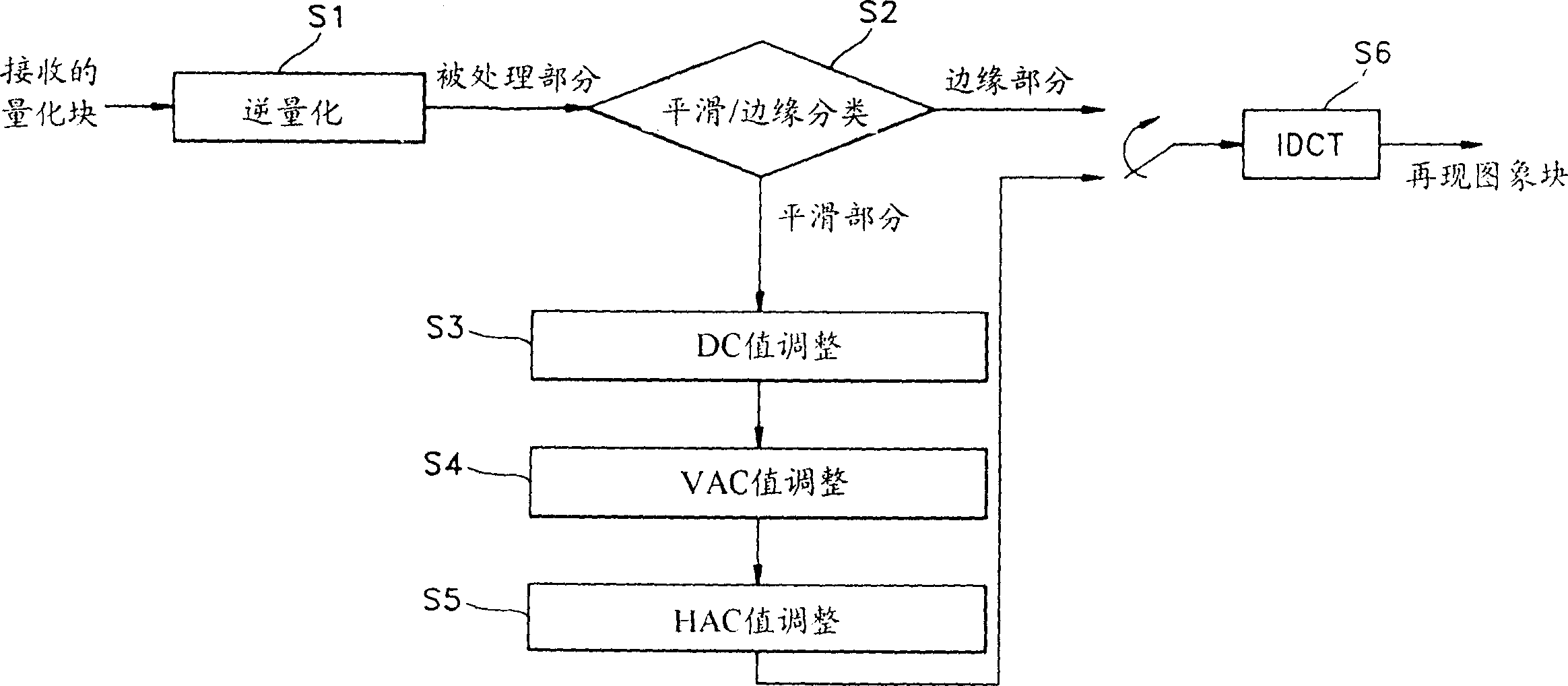
[0030] Since the post-processing method described above takes a weighted average of the DC values ​​of the surrounding blocks during DC value adjustment and performs horizontal and vertical adjustments independently when computing the horizontal and vertical AC adjustment values ​​HAC and VAC, this method is not very effective for removing blocking artifacts. efficient

Method used


Image

  • Post-processing device for eliminating blocking artifact and method thereof
  • Post-processing device for eliminating blocking artifact and method thereof
  • Post-processing device for eliminating blocking artifact and method thereof

Examples


Embodiment Construction

[0052] first by referring to figure 2 An embodiment of a post-processing apparatus and method for removing blocking artifacts is described by illustrating how blocking artifacts are generated.

[0053] figure 2 The input signal to the shown variable length decoder 21 is the quantized transform coefficients QF(u,v). Assuming that F(u, v) represents the transform coefficient without information loss during quantization or inverse quantization, and Fq(u, v) represents the transform coefficient output by the inverse quantizer 22, then F(u, v) can be expressed as:

[0054] F(u,v)=Fq(u,v)+ΔF(u,v) ... (15) where ΔF(u,v) is the information loss in the quantization step, which is the cause of blocking artifacts.

[0055] In the present invention, the value ΔF(u,v) is estimated and subjected to an inverse transformation operation. The inversely transformed adjustment value is then added to the signal fq(x,y), ie the inversely transformed Fq(u,v), in order thereby to effe...


PUM


Abstract

A post-processing device for eliminating a blocking artifact generated upon reconstructing an image compressed by block transform operation and a method thereof minimize a blocking artifact at block boundaries by selecting a predetermined a discrete cosine transform (DCT), estimating transform coefficients with respect to the information lost upon quantization or inverse quantization to have the highest continuity with respect to adjacent blocks, performing inverse transform operation on the estimated transform coefficients, and adding the thus-obtained adjustment value to an inverse-transform-operated reconstructed image signal.

Description

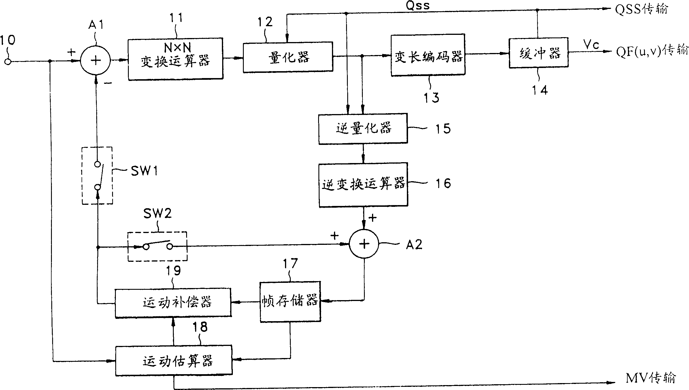
technical field [0001] The present invention relates to a post-processing device and method for eliminating blocking artifacts, in particular to a post-processing device for minimizing blocking artifacts in adjacent blocks for restoring image data compressed by block transform operations and methods. Background technique [0002] There are various standard methods of encoding video (and audio) signals into digital signals for transmission or storage and decoding the transmitted or stored digital signals for reproduction. However, these methods generate enormous amounts of encoded digital video data. Therefore, in order to reduce the total amount of data, redundancies contained in digital image signals are eliminated using, for example, transform coding, differential pulse code modulation, quantization, and variable length coding. [0003] figure 1 is a block diagram schematically showing a general image data encoder. The apparatus generally includes means 11 and 12 for t...

Claims


Application Information

Patent Timeline
IPC IPC(8): H04N5/92G06T9/00H04N1/41H04N19/102H04N19/134H04N19/14H04N19/154H04N19/176H04N19/196H04N19/44H04N19/60H04N19/625H04N19/85H04N19/86
CPCH04N19/00909H04N19/00593H04N19/527H04N19/86H04N19/625
Inventor 全炳宇郑济昌
Owner SAMSUNG ELECTRONICS CO LTD
Learn More