Mounting structure of concentric thin-wall hollow shaft and main hand tool

An installation structure and hollow shaft technology, which is applied in the field of medical devices, can solve the problems of reducing the wall thickness of concentric thin-walled hollow shafts and limiting the minimum value of wall thickness, etc., and achieve the effect of reducing the overall size and roughly equal bending strength

Pending Publication Date: 2021-07-16
CHONGQING JINSHAN MEDICAL ROBOTICS CO LTD
View PDF0 Cites 0 Cited by
  • Summary
  • Abstract
  • Description
  • Claims
  • Application Information

AI Technical Summary

Problems solved by technology

[0003] For the concentric thin-walled hollow shaft, in order to minimize its outer diameter, it is necessary to reduce the wall thickness of the concentric thin-walled hollow shaft. Under the premise of ensuring a certain axial bending resistance, the minimum value of the wall thickness is limited.

Method used


Image

  • Mounting structure of concentric thin-wall hollow shaft and main hand tool
  • Mounting structure of concentric thin-wall hollow shaft and main hand tool
  • Mounting structure of concentric thin-wall hollow shaft and main hand tool

Examples


Embodiment Construction

[0024] The present invention will be further described below in conjunction with the accompanying drawings and embodiments. It should be noted that in the description of the present invention, the terms "upper", "lower", "left", "right", "inner", "outer" etc. The indicated orientation or positional relationship is based on the orientation or positional relationship shown in the drawings, and is only for the convenience of describing the present invention and simplifying the description, rather than indicating or implying that the referred device or element must have a specific orientation or in a specific way construction and operation, therefore, should not be construed as limiting the invention. The terms "first", "second", "third", etc. are used for descriptive purposes only and should not be construed as indicating or implying relative importance.

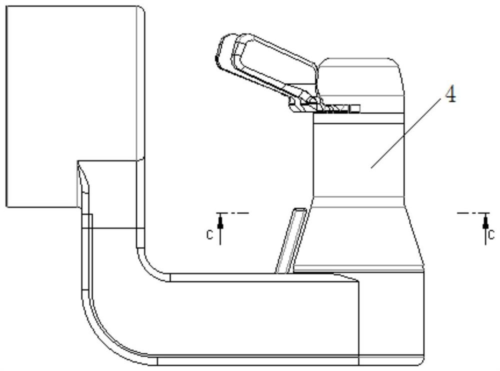
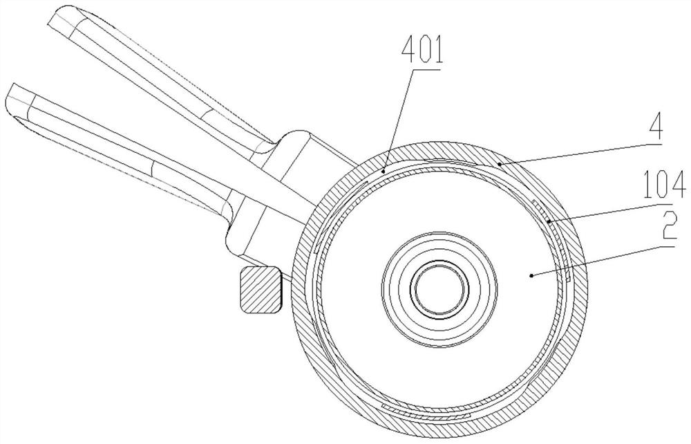
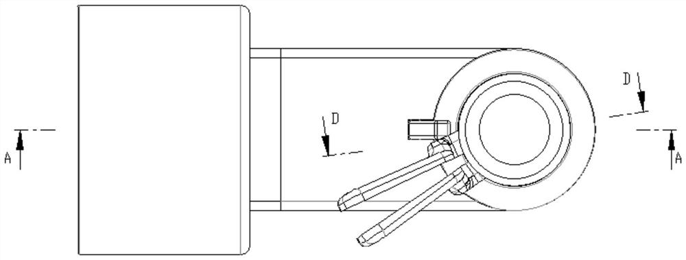
[0025] Such as Figure 1-Figure 9 As shown, an installation structure of a concentric thin-walled hollow shaft includes an e...


PUM


Abstract

The invention discloses a mounting structure of a concentric thin-wall hollow shaft and a main hand tool. The mounting structure of the concentric thin-wall hollow shaft comprises an electric shell; a hollow flange shaft which is in clearance fit with the electric shell is arranged in the electric shell, and a plurality of concave parts which are arranged at intervals are arranged on the inner side face of the lower end of the electric shell; and the lower end of the flange shaft is an inserting part corresponding to the concave part, and the arc length corresponding to the inserting part is smaller than the arc length corresponding to the concave part. According to the mounting structure of the concentric thin-wall hollow shaft, the solid parts of the electric shell and the flange shaft are overlapped in the radial direction and are evenly distributed in the circumferential direction in a staggered mode, the axial rigidity of the electric shell and the flange shaft is guaranteed, the boundary dimension is reduced, and it can be guaranteed that the bending strength of the electric shell and the bending strength of the flange shaft in all directions are roughly equal.

Description

technical field [0001] The invention relates to a medical device, in particular to a mounting structure of a concentric thin-walled hollow shaft and a main hand tool. Background technique [0002] The main hand tools of Da Vinci SI and XI are connected to the main hand, and the chief surgeon controls the position and posture of the instruments in the patient's body by holding the main hand tool; it is controlled by manipulating the opening and closing of the two triggers with the finger and index finger or middle finger Opening and closing of instrument jaws inside the patient. When the surgeon controls the movement of the main hand tool to the edge of the operable area, press the clutch button on the main hand tool, the mapping connection between the main hand and the slave hand and the instrument is disconnected, drag the main hand tool back to the initial position, Release the clutch button, the master hand and the slave hand, and the mapping of the instrument restores t...

Claims


Application Information

Patent Timeline
Patent Type & Authority Applications(China)
IPC IPC(8): A61B34/37
CPCA61B34/37A61B34/71A61B34/74
Inventor 王了王勇
Owner CHONGQING JINSHAN MEDICAL ROBOTICS CO LTD
Why Eureka
Try Eureka