
Numerical control machine tool spindle axial thermal error physical modeling method

A modeling method and technology of CNC machine tools, applied in the directions of simulator, program control, computer control, etc., can solve the problems of increased compensation cost, multiple sensors, and multiple hyperparameters, etc., to achieve convenient post-compensation, strong generalization ability, and step-by-step simple effect

Active Publication Date: 2021-07-16
SICHUAN UNIV
View PDF28 Cites 0 Cited by
  • Summary
  • Abstract
  • Description
  • Claims
  • Application Information

AI Technical Summary

Problems solved by technology

[0004] At present, there are a large number of literatures on the axial thermal error of the spindle, but there are the following problems: (1) only consider the axial thermal error of the spindle caused by the spindle temperature, and ignore the ambient temperature and column temperature on the axial thermal error of the spindle; (2) ) requires more sensors, which increases the compensation cost and may affect the actual processing; (3) the BP neural network method is mainly used to calculate the axial thermal error of the spindle. These methods require many hyperparameters, and it is difficult to find the optimal parameters in practical applications. , it is easy to lead to over-fitting of the model, which eventually leads to insufficient generalization ability and affects the accuracy of later compensation; and these methods are only statistically significant, without machine tool structural parameters, and have no physical meaning

Method used


Image

  • Numerical control machine tool spindle axial thermal error physical modeling method
  • Numerical control machine tool spindle axial thermal error physical modeling method
  • Numerical control machine tool spindle axial thermal error physical modeling method

Examples


Embodiment Construction

[0044] A physical modeling method for axial thermal error of a numerically controlled machine tool spindle provided in this embodiment includes the following steps:

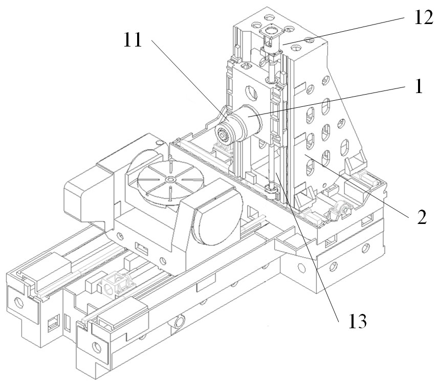
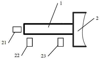
[0045] (A) Install a temperature sensor on the machine tool, the temperature sensor includes 4, which are used to measure the temperature T of the spindle 1 S The first temperature sensor is used to measure the temperature T of the upper part of the column 2 C1 The second temperature sensor is used to measure the temperature T of the lower part of the column 2 C2 The third temperature sensor and used to measure the ambient temperature T amb The fourth temperature sensor, such as figure 1 As shown, the installation location 11 of the first temperature sensor, the installation location 12 of the second temperature sensor, the installation location 13 of the third temperature sensor, and the installation location of the fourth temperature sensor is installed on a fixture near the machine tool, such as on a wall o...


PUM


Abstract

The invention discloses a numerical control machine tool spindle axial thermal error physical modeling method, which comprises the following steps that (A) installing temperature sensors on a machine tool, wherein the temperature sensors comprise a first temperature sensor, a second temperature sensor, a third temperature sensor and a fourth temperature sensor; (B) establishing a thermal error linear sub-model of the main shaft only caused by environment temperature change; (C) establishing a thermal error linear sub-model, which is only caused by the temperature change of the main shaft, of the main shaft; (D) establishing a thermal error nonlinear sub-model of the main shaft only caused by the temperature change of the stand column; and (E) establishing a superposition model containing the error components. According to the main shaft axial thermal error model, machine tool structure parameters are considered, only four temperature sensors are needed, the model generalization ability is high, physical significance is achieved, programming is easy to achieve, and technical support is provided for later thermal error compensation application.

Description

technical field [0001] The invention belongs to the field of thermal error modeling and compensation of a main shaft in the thermal precision control of a numerical control machine tool, and in particular relates to a physical modeling method for the axial thermal error of the main shaft of a numerical control machine tool. Background technique [0002] The processing accuracy of parts is mainly determined by the accuracy of processing equipment; CNC machine tools are widely used in the processing of complex curved surface parts in the automotive, aerospace, shipbuilding and other industries. In order to achieve better product quality, these parts have higher and higher requirements for machining accuracy; therefore, there are higher requirements for the accuracy of CNC machine tools. Among the many factors affecting the accuracy of the machine tool, the deformation of the machine tool caused by thermal load and the resulting thermal error are the most critical factors affec...

Claims


Application Information

Patent Timeline
Patent Type & Authority Applications(China)
IPC IPC(8): G05B19/408
CPCG05B19/4086G05B2219/35356
Inventor 殷鸣彭骥曹利蒲耀洲邵圳王玲殷国富
Owner SICHUAN UNIV
Learn More