
A kind of foundation pit supporting structure and construction method thereof

A foundation pit support and construction method technology, which is applied in the direction of foundation structure engineering, excavation, construction, etc., can solve the problems of decreased soil stiffness, increased horizontal displacement, and large horizontal displacement, so as to improve the control of deformation and improve the soil quality. body stiffness, reducing the effect of deformation

Active Publication Date: 2022-03-08
昆山瑾晖城市建设基金会
View PDF11 Cites 0 Cited by
  • Summary
  • Abstract
  • Description
  • Claims
  • Application Information

AI Technical Summary

Problems solved by technology

But the problem is that the support structure cannot intercept the infiltration of groundwater outside the pit, and the disturbance of the anchor pile to the soil outside the pit is not low. The soil strain in the small strain area at the edge of the pit gradually increases, and the soil stiffness decreases sharply
[0005] The Chinese patent with the application number CN202011317573.9 discloses a steel-concrete combination foundation pit support structure. The steel sheet pile itself forms a waterproof structure. One end of the connecting steel bar is fixed on the steel sheet pile, and the other end of the connecting steel bar passes through the ring beam. and extend into the secondary beam, and the corbel support is set under the secondary beam, but the problem is that when the soil outside the pit has a greater tendency to move into the pit, it can only rely on the horizontal support force of the inner support. Compared with common internal support and concrete crown beam connection, the principle of controlling deformation is not much different
[0006] In general, the existing technology fails to fully consider the small strain characteristics of the soil, and ignores the nonlinear variation characteristics of soil stiffness with strain in the small strain area. Although the existing support methods can be used to a certain extent It plays the role of controlling the horizontal displacement of the soil outside the pit and the enclosure structure, but the measures taken also increase the horizontal displacement to a certain extent

Method used


Image

  • A kind of foundation pit supporting structure and construction method thereof
  • A kind of foundation pit supporting structure and construction method thereof
  • A kind of foundation pit supporting structure and construction method thereof

Examples


Embodiment Construction

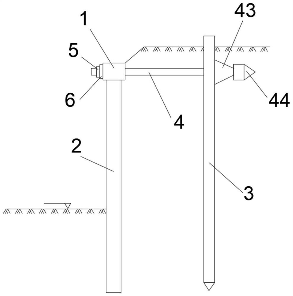
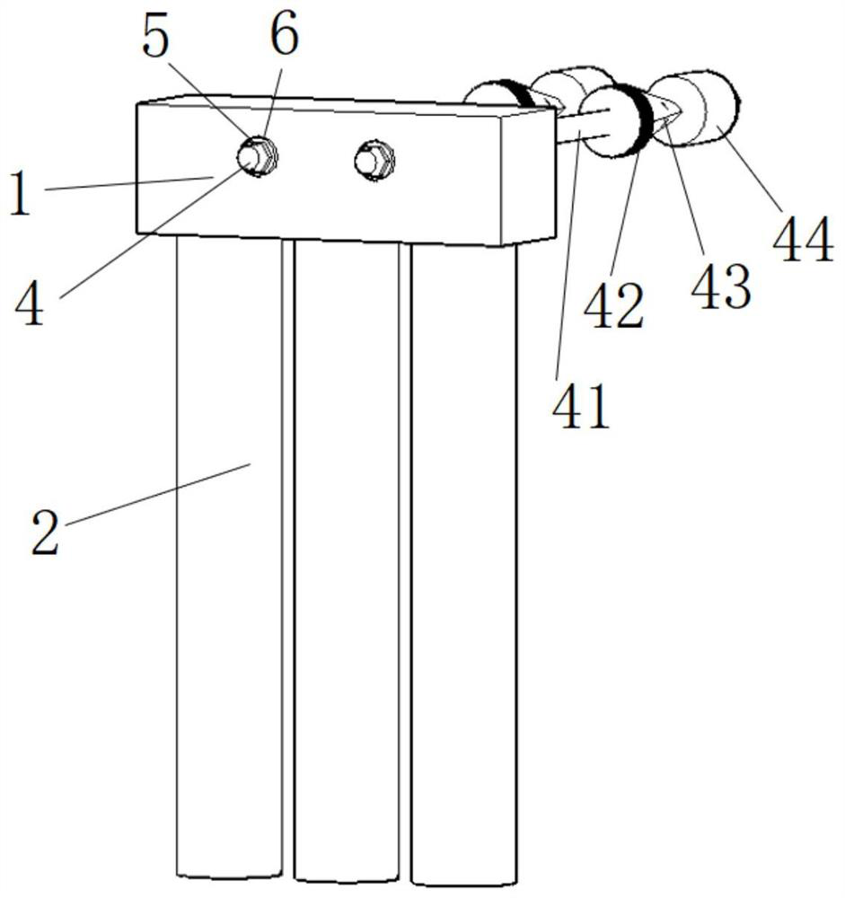
[0035] Such as Figure 1~2 , the foundation pit support structure includes crown beam 1, row of piles 2, steel plate wall 3 and tie rod 4, the insertion depth of steel plate wall 3 should be determined according to the hydrogeological conditions of the actual project, the vertical plane where crown beam 1 is located and the steel plate wall 3 The distance between the vertical planes should be determined according to the distance between the red line of the project land and the sideline of the foundation pit and the specific conditions of the surrounding environment. Preferably, the crown beam 1 is set at the critical depth of the foundation pit, that is, the maximum inflection point, which is the maximum theoretical deformation position of the foundation pit, and measures should be taken to control it. In the relative positions of tie rod 4, crown beam 1 and pile row 2, tie tie rod 4 should avoid pile row 2 and be inserted into crown beam 1 position. The tie rod 4 is fixedly ...


PUM


Abstract

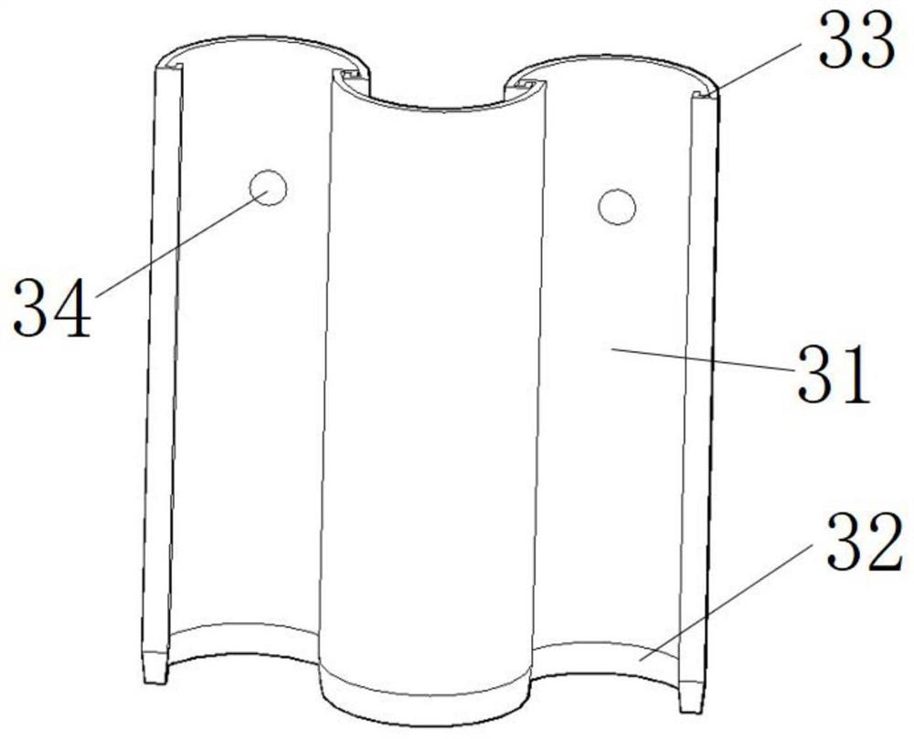
The invention discloses a foundation pit supporting structure, which comprises a crown beam, row piles, a steel plate wall and tie rods, the crown beam is connected with the row piles, one end of the tie rod is connected with the crown beam, the other end passes through the steel plate wall and Inserted into the soil, the steel plate wall consists of several steel plates. The bottom of the steel plate is provided with a cone tip, and the two sides of the steel plate are provided with grooves. The arc-shaped steel plates are connected together to form a steel plate wall. When the soil around the foundation pit tends to move into the pit, the wave-shaped steel plate wall can provide a large reaction force and control the deformation of the soil. Threaded holes are set on the steel plate. The invention also discloses a construction method of the foundation pit supporting structure. For the foundation pit project that requires strict control of deformation, the foundation pit support structure of the present invention is adopted, and the steel plate wall and the crown beam are tightened to form a whole through the tie rods of a special structure, which improves the stiffness of the soil body and can effectively control the foundation pit and deformation of the surrounding soil.

Description

technical field [0001] The invention relates to a supporting structure and a manufacturing method thereof, in particular to a foundation pit supporting structure and a construction method thereof. Background technique [0002] Domestic construction sites are tight, and the utilization of urban underground space projects has entered a stage of rapid development. This has led to an increase in the number, excavation depth, and scale of foundation pit projects in China. At the same time, many cities are carrying out large-scale In the reconstruction of the old city, many foundation pit projects are located in prosperous building-intensive areas, which undoubtedly increases the difficulty of support and increases the requirements for deformation of foundation pits, support structures and surrounding soil. There are not a few collapse accidents caused by excessive size. [0003] A large number of on-site engineering measurements show that a considerable part of the soil in geote...

Claims


Application Information

Patent Timeline
Patent Type & Authority Patents(China)
IPC IPC(8): E02D17/04
CPCE02D17/04
Inventor 梅岭董鑫
Owner 昆山瑾晖城市建设基金会
Learn More