Supercharge Your Innovation With Domain-Expert AI Agents!

Combined worktable for costume design and operation method

A clothing design and workbench technology, applied in the field of clothing design, can solve problems such as inability to place tools, poor comfort, and single functionality

Inactive Publication Date: 2021-07-23
NANJING FORESTRY UNIV
View PDF11 Cites 0 Cited by
  • Summary
  • Abstract
  • Description
  • Claims
  • Application Information

AI Technical Summary

Problems solved by technology

[0005] The invention provides a combined workbench for clothing design and an operation method, which solves the problem that the existing workbench has a single function. When people use the workbench, they cannot be cut according to the use requirements and cannot be placed for various daily use. tools, and the angle cannot be tilted according to people's needs, which may easily cause people's poor comfort and technical problems that are inconvenient for people to use

Method used


Image

  • Combined worktable for costume design and operation method
  • Combined worktable for costume design and operation method
  • Combined worktable for costume design and operation method

Examples


Embodiment 1

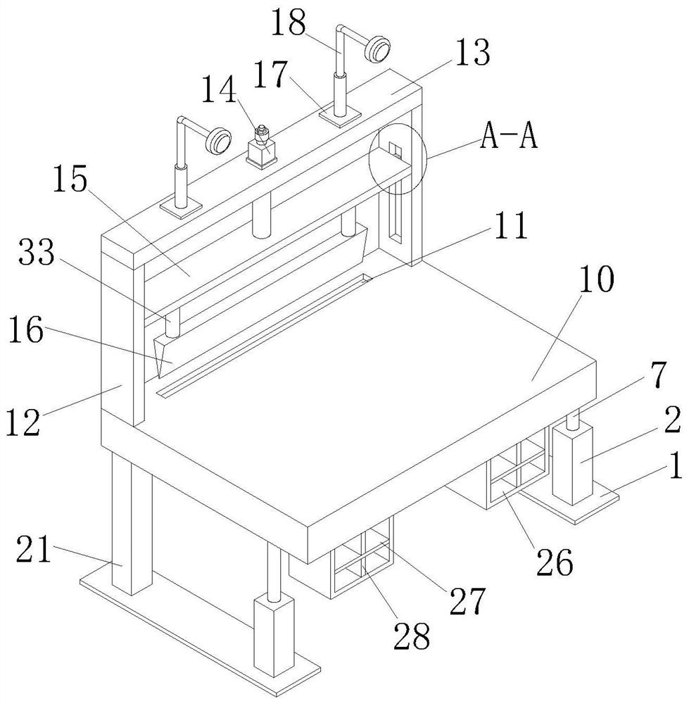
[0030] see Figure 1-4 , the present invention provides a technical solution: a combined workbench for clothing design, including a base plate 1, the number of base plates 1 is two, and the two base plates 1 are left and right symmetrically arranged, and the front side of the top of the base plate 1 is fixedly connected with Housing 2, a stepping motor 3 is fixedly connected to the outer side of the bottom of the inner chamber of the housing 2, and the output end of the stepping motor 3 is fixedly connected to a screw rod 4, and the surface of the screw rod 4 is threadedly connected to a wire sleeve 5, and the wire sleeve 5 The inner side is fixedly connected with a first fixed block 6, and the inner side of the first fixed block 6 is fixedly connected with a support column 7, and the top of the support column 7 is fixedly connected with a concave seat 8, and the inner cavity of the concave seat 8 is movably connected with a connecting block through a pin shaft 9. The top of t...

Embodiment 2

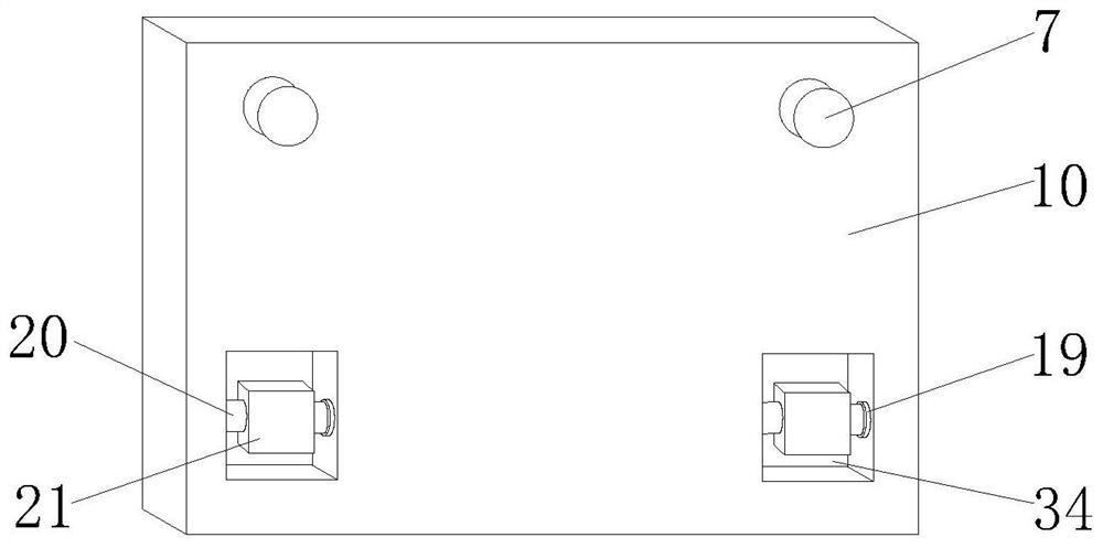
[0033] see Figure 1-4As shown, on the basis of Embodiment 1, the present invention provides a technical solution: both sides of the top of the support plate 13 are fixedly connected with a fixed plate 17, and the top of the fixed plate 17 is fixedly connected with a lighting lamp 18, and the workbench main body 10 The rear sides of both sides of the bottom are provided with grooves 34, and both sides of the inner cavity of the groove 34 are fixedly connected with the first bearing seat 19, and the inner cavity of the first bearing seat 19 is sleeved with the fixed shaft 20, and the fixed shaft 20 The inner side is fixedly connected with a support rod 21, and the bottom of the support rod 21 is fixedly connected with the rear side of the top of the bottom plate 1. The inner side of the side plate 12 is provided with a chute 22, and the inner cavity of the chute 22 is slidably connected with a slider 23. The inner side of the support column 7 is fixedly connected with both side...


PUM


Abstract

The invention discloses a combined worktable for costume design and an operation method, and relates to the field of costume design. The combined type workbench for costume design comprises two bottom plates, and the two bottom plates are arranged in a bilateral symmetry mode; a shell is fixedly connected to the front sides of the tops of the bottom plates; a stepping motor is fixedly connected to the outer side of the bottom of an inner cavity of the shell; a lead screw is fixedly connected to the output end of the stepping motor; and the surface of the screw rod is in threaded connection with a screw sleeve. According to the combined type workbench for costume design and the operation method, during cutting, an operator places cloth on the workbench main body, then an electric push rod is turned on through an external controller, the electric push rod drives a moving plate to move downwards, and the moving plate drives a sliding block to slide in a sliding groove; and meanwhile, the moving plate drives a fixed rod to move downwards, and the fixed rod drives a cutter to move downwards, so that the cutter is matched with a cutting groove to cut the cloth.

Description

technical field [0001] The invention relates to the field of clothing design, in particular to a combined workbench for clothing design and an operation method. Background technique [0002] Fashion design belongs to the category of arts and crafts. It is an art form that combines practicality and artistry. Design means planning, conception, and establishment, as well as imagery, drawing, and modeling. The definition of fashion design is to solve the problem of people wearing clothes. The creative planning and creative act of problems in living systems. [0003] In the process of clothing design, it is necessary to use a workbench in order to be used in the design. At present, the existing workbench has a single function. When people use the workbench, they cannot be cut according to the use requirements, and various Tools for daily use, and cannot be tilted at an angle according to people's use needs, which may easily cause people's poor comfort and be inconvenient for peo...

Claims


Application Information

Patent Timeline
IPC IPC(8): D06H7/00F21V33/00F21V21/14A47B37/00A47B27/02
CPCD06H7/00F21V33/00F21V21/14A47B37/00A47B27/02
Inventor 徐潇刘遵月
Owner NANJING FORESTRY UNIV
Features
  • R&D
  • Intellectual Property
  • Life Sciences
  • Materials
  • Tech Scout
  • Unparalleled Data Quality
  • Higher Quality Content
  • 60% Fewer Hallucinations
Learn More