A hydraulic gripper tool to prevent sticking and clogging
What is Al technical title?
Al technical title is built by PatSnap Al team. It summarizes the technical point description of the patent document.
A technology of hydraulic claws and hand tools, which is applied in the direction of earthwork drilling and production, wellbore/well parts, etc., to achieve the effects of speeding up the throwing speed, saving costs, and increasing the force-bearing area
Active Publication Date: 2022-03-01
SOUTHWEST PETROLEUM UNIV
View PDF14 Cites 0 Cited by
Summary
Abstract
Description
Claims
Application Information
AI Technical Summary
This helps you quickly interpret patents by identifying the three key elements:
Problems solved by technology
Method used
Benefits of technology
Problems solved by technology
The invention can effectively solve problems such as drill sticking or blockage, and achieve the purpose of cost saving
Method used
Image
Click on the blue label to locate the original text in one second.
Reading with bidirectional positioning of images and text.
Examples
Embodiment Construction
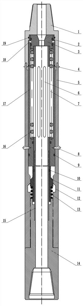
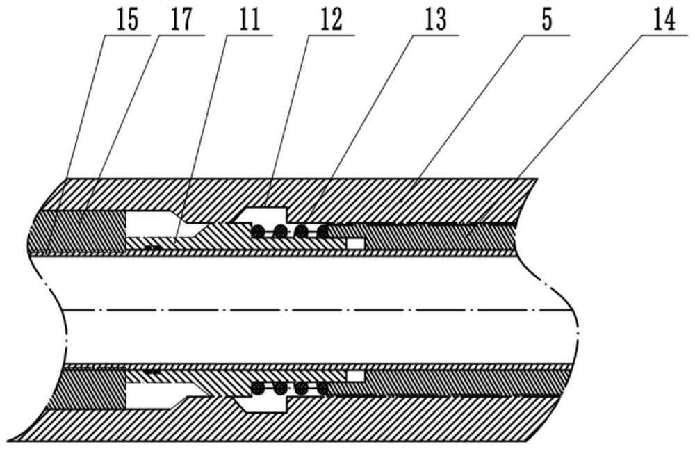
[0013] Such as Figure 1-3 As shown, the tool is a hydraulic gripper tool that prevents drill sticking and blockage. Its structure mainly includes a lower joint 1, an outer cylinder 5, an inner cylinder I15, an upper joint 14, an inner cylinder II17, an elastic gripper 11, Claw grip slot 12, pressure spring 13, piston 3, pin I4, pin II8, spring 16, countersunk screw 18, sealing ring I19, sealing ring II2, sealing ring III9, sealing ring IV10, piston chamber 6, spring chamber Chamber 7; its structural features are: the lower joint 1 cooperates with the outer cylinder 5, the pin I4 is installed at the joint between the lower joint 1 and the outer cylinder 5, the inner cylinder II17 and the piston 3 are connected by countersunk screws 18, and the inner cylinder II17 Installed on the outside of the spring chamber 7 and sealed by two sealing rings I19 and two sealing rings III9, the piston 3 is installed on the inner wall of the inner cylinder II17 and sealed by two sealing rings I...
PUM
Abstract
The invention relates to a hydraulic gripper tool for underground anti-jamming or blockage. Its structure mainly includes: a lower joint, an outer cylinder, an inner cylinder II, an inner cylinder I, an upper joint, an elastic gripper, and a gripper Card slot, pressure spring, sleeve, piston, pin I, pin II, spring, countersunk screw, sealing ring I, sealing ring II, sealing ring III, sealing ring IV, piston chamber, spring chamber; There is a pressure spring in the middle of the elastic gripper, which is installed in the spring slot; when the drill is stuck downhole, the internal pressure increases suddenly, and the piston and inner cylinder II are pushed to cut off the pin II, and the piston and inner cylinder II push the elastic gripper to compress the middle part. The pressure spring makes the claw head of the elastic gripper snap into the gripper groove inside the outer cylinder; the invention has a reasonable structure and is convenient to use.
Description
technical field [0001] The present invention relates to a field related to the drilling and maintenance of oil and gas wells, and is an essential tool for dealing with accidents, and specifically relates to a hydraulic gripper tool for preventing sticking and blockage. Background technique [0002] Many drilling and servicing operations use some kind of downhole tool string, which may be drill pipe or tubing, etc., installed in the wellbore above the string. A tool string may include a number of downhole tools that are all connected to the string or to each other. Without some sort of hands-off mechanism between the motor and the casing cutting tool, not only would the cutting tool get stuck, but other tools above it would also get stuck. [0003] The throwing mechanism in the prior art usually adopts a ball-throwing type. The throwing ball enters the throwing mechanism through the pipe, and forms a seal after reaching the ball seat. The hydraulic pressure pushes the ball d...
Claims
Application Information
Patent Timeline
Application Date:The date an application was filed.
Publication Date:The date a patent or application was officially published.
First Publication Date:The earliest publication date of a patent with the same application number.
Issue Date:Publication date of the patent grant document.
PCT Entry Date:The Entry date of PCT National Phase.
Estimated Expiry Date:The statutory expiry date of a patent right according to the Patent Law, and it is the longest term of protection that the patent right can achieve without the termination of the patent right due to other reasons(Term extension factor has been taken into account ).
Invalid Date:Actual expiry date is based on effective date or publication date of legal transaction data of invalid patent.
