Hydraulic claw hand tool for preventing drill jamming and blockage

A hand tool and hydraulic claw technology, which is applied in the field of hydraulic claw hand tools to prevent sticking and clogging, and achieves the effects of speeding up the throwing speed, saving costs, and increasing the force-bearing area.

Active Publication Date: 2021-07-23
SOUTHWEST PETROLEUM UNIV
View PDF14 Cites 2 Cited by
  • Summary
  • Abstract
  • Description
  • Claims
  • Application Information

AI Technical Summary

Problems solved by technology

The invention can effectively solve problems such as drill sticking or blockage, and achieve the purpose of cost saving

Method used


Image

  • Hydraulic claw hand tool for preventing drill jamming and blockage
  • Hydraulic claw hand tool for preventing drill jamming and blockage
  • Hydraulic claw hand tool for preventing drill jamming and blockage

Examples


Embodiment Construction

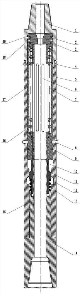
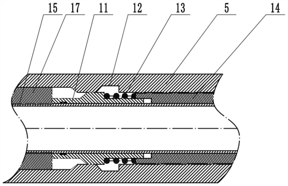
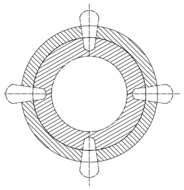
[0013] Such as Figure 1-3 As shown, the tool is a hydraulic gripper tool that prevents drill sticking and blockage. Its structure mainly includes a lower joint 1, an outer cylinder 5, an inner cylinder I15, an upper joint 14, an inner cylinder II17, an elastic gripper 11, Claw grip slot 12, pressure spring 13, piston 3, pin I4, pin II8, spring 16, countersunk screw 18, sealing ring I19, sealing ring II2, sealing ring III9, sealing ring IV10, piston chamber 6, spring chamber Chamber 7; its structural features are: the lower joint 1 cooperates with the outer cylinder 5, the pin I4 is installed at the joint between the lower joint 1 and the outer cylinder 5, the inner cylinder II17 and the piston 3 are connected by countersunk screws 18, and the inner cylinder II17 Installed on the outside of the spring chamber 7 and sealed by two sealing rings I19 and two sealing rings III9, the piston 3 is installed on the inner wall of the inner cylinder II17 and sealed by two sealing rings I...


PUM


Abstract

The invention relates to a hydraulic claw hand tool for preventing drill jamming or blockage underground. The hydraulic claw hand tool structurally and mainly comprises a lower connector, an outer cylinder, an inner cylinder II, an inner cylinder I, an upper connector, an elastic claw hand, a claw hand clamping groove, a pressure spring, a sleeve, a piston, a pin I, a pin II, a spring, a sunk screw, a sealing ring I, a sealing ring II, a sealing ring III, a sealing ring IV, a piston cavity and a spring cavity; the middle part of the elastic claw hand is provided with the pressure spring which is arranged in a spring clamping groove; when a drill is stuck underground, the internal pressure is increased suddenly, the piston and the inner cylinder II are pushed to shear off the pin II, and the piston and the inner cylinder II push the elastic claw hand to compress the pressure spring in the middle of the elastic claw hand, so that the claw head of the elastic claw hand is clamped into the claw hand clamping groove in the inner side of the outer cylinder. The hydraulic claw hand tool is reasonable in structure and convenient to use.

Description

technical field [0001] The present invention relates to a field related to the drilling and maintenance of oil and gas wells, and is an essential tool for dealing with accidents, and specifically relates to a hydraulic gripper tool for preventing sticking and blockage. Background technique [0002] Many drilling and servicing operations use some kind of downhole tool string, which may be drill pipe or tubing, etc., installed in the wellbore above the string. A tool string may include a number of downhole tools that are all connected to the string or to each other. Without some sort of hands-off mechanism between the motor and the casing cutting tool, not only would the cutting tool get stuck, but other tools above it would also get stuck. [0003] The throwing mechanism in the prior art usually adopts a ball-throwing type. The throwing ball enters the throwing mechanism through the pipe, and forms a seal after reaching the ball seat. The hydraulic pressure pushes the ball d...

Claims


Application Information

Patent Timeline
Patent Type & Authority Applications(China)
IPC IPC(8): E21B23/00E21B31/12
CPCE21B23/00E21B31/12
Inventor 石昌帅李保红祝效华
Owner SOUTHWEST PETROLEUM UNIV
Why Eureka
Try Eureka