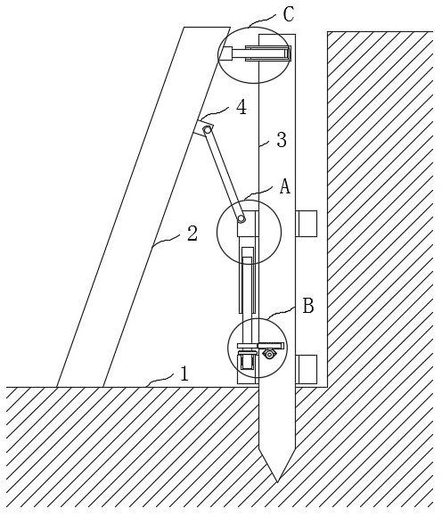
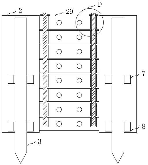
Inclined pile vertical anchor supporting structure adjacent to existing building foundation pit

A technology for existing buildings and supporting structures, applied in infrastructure engineering, construction, excavation, etc., can solve the problems of the deviation of the inclination of the retaining wall, and the inclination angle is not easy to adjust according to the needs, so as to avoid deviation and improve the supporting effect. , the effect of simple operation

Inactive Publication Date: 2021-07-27
高晓枝
View PDF0 Cites 0 Cited by
  • Summary
  • Abstract
  • Description
  • Claims
  • Application Information

AI Technical Summary

Problems solved by technology

[0002] In the process of building construction, it is necessary to excavate the earth pit at the foundation design position according to the base elevation and foundation plane size according to the geological and hydrological data and the conditions of the nearby buildings. When the foundation pit is excavated next to the building, it is often necessary to The side wall of the foundation pit is set to run on a slope, so as to improve the stability of the adjacent buildings. At this time, the pile beams supporting the side wall of the foundation pit also need to be set at an inclination, but when the existing inclined piles are installed, the inclination angle It is not easy to adjust according to the needs, resulting in deviations in the slope of the retaining wall after pouring, so it is urgent to design a vertical anchor support structure for inclined piles adjacent to the existing building foundation pit

Method used


Image

  • Inclined pile vertical anchor supporting structure adjacent to existing building foundation pit
  • Inclined pile vertical anchor supporting structure adjacent to existing building foundation pit
  • Inclined pile vertical anchor supporting structure adjacent to existing building foundation pit

Examples


Embodiment Construction

[0030] The following will clearly and completely describe the technical solutions in the embodiments of the present invention with reference to the accompanying drawings in the embodiments of the present invention. Obviously, the described embodiments are only some, not all, embodiments of the present invention. Based on the embodiments of the present invention, all other embodiments obtained by persons of ordinary skill in the art without making creative efforts belong to the protection scope of the present invention.

[0031] In describing the present invention, it should be understood that the terms "upper", "lower", "front", "rear", "left", "right", "top", "bottom", "inner", " The orientation or positional relationship indicated by "outside", etc. is based on the orientation or positional relationship shown in the drawings, and is only for the convenience of describing the present invention and simplifying the description, rather than indicating or implying that the referre...


PUM


Abstract

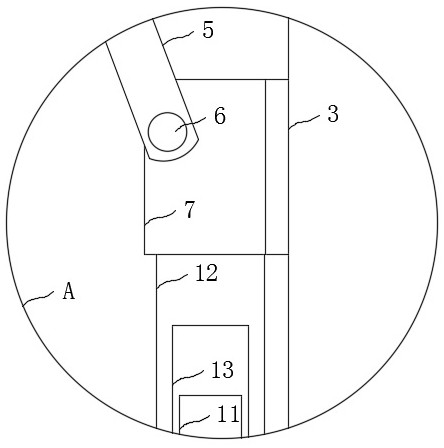
The invention discloses an inclined pile vertical anchor supporting structure adjacent to an existing building foundation pit. The inclined pile vertical anchor supporting structure comprises two inserting rods fixedly arranged on a pit body of the building foundation pit, wherein inclined piles are arranged on the two inserting rods; hinging seats are fixedly arranged on the two inclined piles; the two hinging seats are rotationally connected with connecting rods through rotating rods; sliding sleeves are slidingly connected onto the two inserting rods; in addition, the two sliding sleeves are rotationally connected with the other ends of the two connecting rods through rotating rods; fixing sleeves are fixedly arranged on the two inserting rods; supporting ascending and descending mechanisms are arranged between the two fixing sleeves and the two sliding sleeves; and a plurality of cross beams are slidingly connected between the two inclined piles. The inclined pile vertical anchor supporting structure has the advantages that the angles of the inclined piles relative to the inserting rods can be adjusted according to requirements, so that the inclination angle of the formed retaining wall can be ensured to be a preset value, the occurrence of the deviation is avoided, the angle adjustment operation of the inclined piles is simple and convenient, and the operation difficulty can be reduced.

Description

technical field [0001] The invention relates to the technical field of foundation pit support, in particular to an inclined pile vertical anchor support structure for adjacent to existing building foundation pits. Background technique [0002] In the process of building construction, it is necessary to excavate the earth pit at the foundation design position according to the base elevation and foundation plane size according to the geological and hydrological data and the conditions of the nearby buildings. When the foundation pit is excavated next to the building, it is often necessary to The side wall of the foundation pit is set to run on a slope, so as to improve the stability of the adjacent buildings. At this time, the pile beams supporting the side wall of the foundation pit also need to be set at an inclination, but when the existing inclined piles are installed, the inclination angle It is difficult to adjust according to the needs, resulting in deviations in the in...

Claims


Application Information

Patent Timeline
IPC IPC(8): E02D17/04
CPCE02D17/04
Inventor 高晓枝
Owner 高晓枝
Why Eureka
Try Eureka