A positioning device and motor

A technology for positioning devices and positioning parts, which is applied in the direction of electromechanical devices, electric components, electrical components, etc., can solve the problem that the rotor shell cannot be positioned at a fixed angle, and achieve the effect of speeding up the stop time and overcoming inertial rotation

Active Publication Date: 2022-05-17
肇庆凌飞航空科技有限公司
View PDF14 Cites 0 Cited by
  • Summary
  • Abstract
  • Description
  • Claims
  • Application Information

AI Technical Summary

Problems solved by technology

[0004] However, conventional motors cannot position the rotor housing at a fixed angle when stopped

Method used


Image

  • A positioning device and motor
  • A positioning device and motor

Examples


Embodiment Construction

[0033] Embodiments of the present invention are described in detail below, examples of which are shown in the drawings, wherein the same or similar reference numerals designate the same or similar elements or elements having the same or similar functions throughout. The embodiments described below by referring to the figures are exemplary only for explaining the present invention and should not be construed as limiting the present invention.

[0034] In the description of the present invention, it should be understood that the orientation descriptions, such as up, down, front, back, left, right, etc. indicated orientations or positional relationships are based on the orientations or positional relationships shown in the drawings, and are only In order to facilitate the description of the present invention and simplify the description, it does not indicate or imply that the device or element referred to must have a specific orientation, be constructed and operated in a specific ...


PUM


Abstract

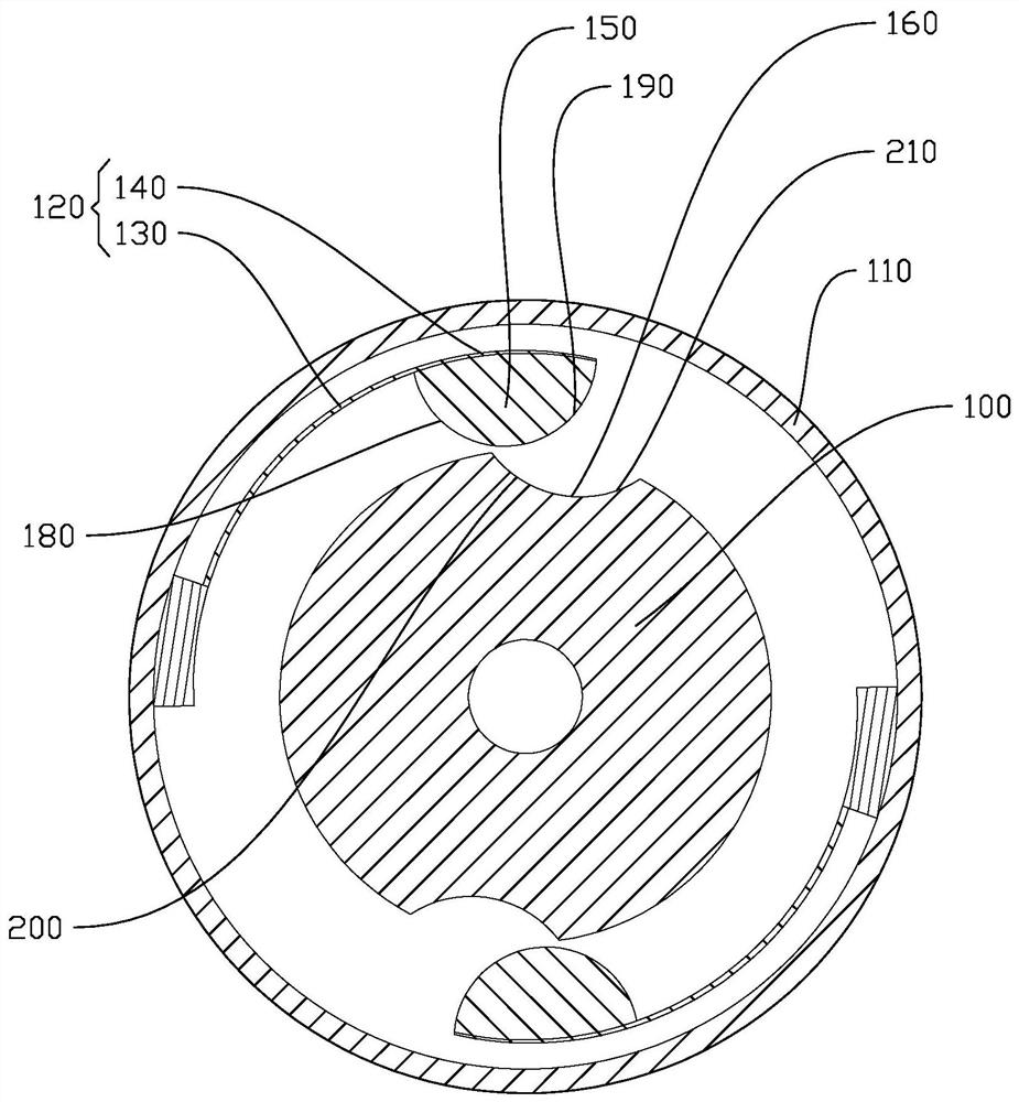
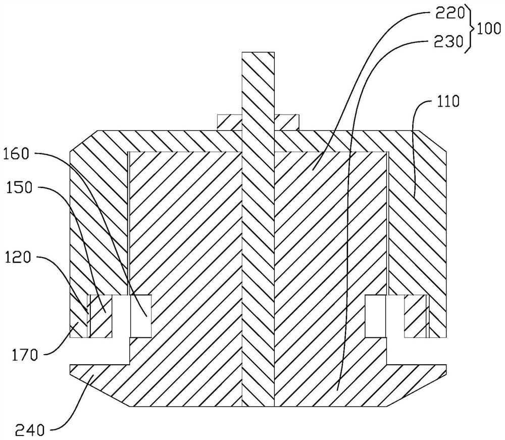
The invention discloses a positioning device, and discloses a motor with the positioning device. One of the positioning devices includes a stator and a rotor casing. It is characterized in that the rotor casing is provided with a positioning piece, and the positioning piece includes an elastic part connected with the rotor casing and a positioning part connected with the elastic part. A protrusion is arranged between the positioning part and the stator. The body and the concave part for accommodating the convex body, the convex body and the concave part are positioned in cooperation, and the rotation of the rotor shell drives the convex body and the concave part away from each other. A positioning device of the present invention can position the rotor casing when the motor stops rotating.

Description

technical field [0001] The invention relates to the field of motors, in particular to a positioning device and a motor. Background technique [0002] Motor refers to an electromagnetic device that realizes electric energy conversion or transmission according to the law of electromagnetic induction, and its main function is to generate driving torque. [0003] The electric machine has a stator and a rotor housing. [0004] However, conventional motors cannot position the rotor housing at a fixed angle when it stops rotating. Contents of the invention [0005] The present invention aims to solve at least one of the technical problems existing in the prior art. Therefore, the present invention proposes a positioning device capable of positioning the rotor casing when the motor stops rotating. [0006] The present invention also proposes a motor with the above positioning device. [0007] A positioning device according to an embodiment of the first aspect of the present in...

Claims


Application Information

Patent Timeline
Patent Type & Authority Patents(China)
IPC IPC(8): H02K1/28H02K7/12H02K7/102H02K5/04H02K5/10
CPCH02K1/28H02K7/12H02K7/102H02K5/04H02K5/10
Inventor 孔凌植雅芳
Owner 肇庆凌飞航空科技有限公司
Why Eureka
Try Eureka