
Gynecological and obstetrical examination chair

A technology of obstetrics and gynecology and chairs, which is applied in dental chairs, dentistry, operating chairs, etc., can solve the problems of inconvenient adjustment, unfavorable inspection and diagnosis of leg opening angle, inconvenient and flexible adjustment of seat height, etc., and achieve reasonable design , easy to adjust flexibly, easy to check the effect of diagnostic work

Pending Publication Date: 2021-07-30
黑龙江省医院
View PDF7 Cites 0 Cited by
  • Summary
  • Abstract
  • Description
  • Claims
  • Application Information

AI Technical Summary

Problems solved by technology

[0003] The existing obstetrics and gynecology examination chairs are provided with two leg dragging boards, and the patient places the legs on the corresponding leg dragging boards to realize the stretching action of the legs, but the support height of the leg dragging boards and The distance between the two leg mopping boards is mostly fixed, and it is not convenient to adjust according to actual needs, and there is a disadvantage that it is not convenient to automatically adjust the lifting height and opening angle of the patient's legs. Most patients will suffer from tension and discomfort. The angle at which the legs are stretched is not conducive to the doctor's examination and diagnosis, and the height of the seat is not easy to adjust flexibly according to the actual needs, which cannot meet the needs of use. Based on the above conditions, we have improved it. Therefore, we propose an obstetrics and gynecology examination The seat is used to solve the above problems

Method used


Image

  • Gynecological and obstetrical examination chair
  • Gynecological and obstetrical examination chair
  • Gynecological and obstetrical examination chair

Examples


Embodiment

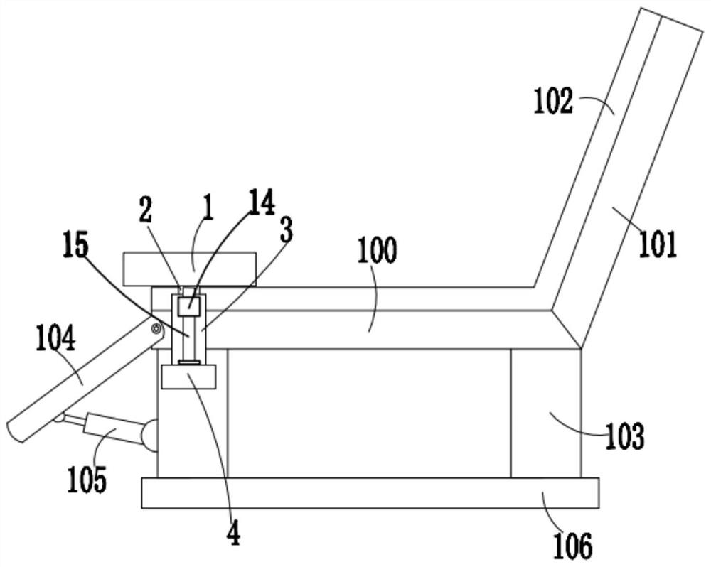
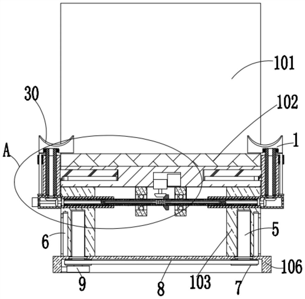
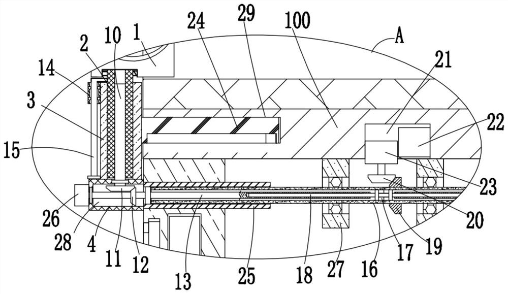
[0027] refer to Figure 1-4, the present embodiment proposes an obstetrics and gynecology examination seat, including an examination seat body, an examination seat body including a seat board 100 and an obliquely arranged backrest 101 fixedly installed on the right side of the seat board 100, and the top of the seat board 100 The same sponge cushion 102 is bonded and fixed to the left side of the backrest 101, and the four corners of the bottom of the seat board 100 are fixedly connected with support legs 103, and the left side of the seat board 100 is rotated to be equipped with a foot placement plate 104, four support legs 103 The left sides of the two support legs 103 on the left side are all rotated and installed with an electric telescopic rod 105 that is arranged obliquely upward. The output end of the electric telescopic rod 105 is hinged with the bottom right side of the foot placement plate 104. The bottom of 103 is in movable contact with a box-shaped base plate 106 ...


PUM


Abstract

The invention discloses a gynecological and obstetrical examination chair which comprises an examination seat body, the examination seat body comprises a seat plate and a backrest which is fixedly installed on the right side of the seat plate and is obliquely arranged, the top of the seat plate and the left side of the backrest are fixedly bonded with the same sponge cushion, and the four corners of the bottom of the seat plate are fixedly connected with supporting legs; a foot placing plate is rotatably mounted on the left side of the seat plate, electric telescopic rods which are obliquely arranged upwards are rotatably mounted on the left sides of the two supporting legs, located on the left side, in the four supporting legs, and the output ends of the electric telescopic rods are hinged to the bottom of the right side of the foot placing plate. According to the invention, the design is reasonable, the height of the seat plate can be flexibly adjusted according to use requirements, the legs of a patient can be automatically lifted up, the patient does not need to lift up the legs with effort, the two leg dragging plates can be synchronously adjusted to move in the direction away from each other, and the purpose of automatically opening the legs of the patient outwards and adjusting the angle is achieved, and doctors can conveniently perform examination and diagnosis work.

Description

technical field [0001] The invention relates to the technical field of examination chairs, in particular to an examination chair in obstetrics and gynecology. Background technique [0002] The obstetrics and gynecology department needs to conduct a routine vulva examination. The vulva examination will observe the color and appearance of the female vulva, as well as whether there are ulcers, dermatitis, vegetations, and hypopigmentation in the perineal area. During the examination, the patient needs to sit in a chair Stretch the legs up to facilitate the doctor's examination and diagnosis; [0003] The existing obstetrics and gynecology examination chairs are provided with two leg dragging boards, and the patient places the legs on the corresponding leg dragging boards to realize the stretching action of the legs, but the support height of the leg dragging boards and The distance between the two leg mopping boards is mostly fixed, and it is not convenient to adjust according...

Claims


Application Information

Patent Timeline
IPC IPC(8): A61G15/02A61G15/10A61G15/12
CPCA61G15/02A61G15/10A61G15/12A61G15/005A61G2200/12
Inventor 王轶婷郭昕
Owner 黑龙江省医院
Learn More