
Road engineering concrete vibrating device

A vibrating device and technology for road engineering, applied in the direction of roads, roads, road repair, etc., can solve the problems of increasing the labor intensity and inconvenience of operators, and achieve the effects of expanding the scope of vibrating, facilitating the vibrating, and facilitating the operation.

Pending Publication Date: 2021-07-30
CHINA FIRST METALLURGICAL GROUP
View PDF11 Cites 0 Cited by
  • Summary
  • Abstract
  • Description
  • Claims
  • Application Information

AI Technical Summary

Problems solved by technology

[0002] In road engineering, it is necessary to use a vibrating device to vibrate concrete, but the current vibrating device requires the operator to move the device frequently, so that other areas can be vibrated, which is extremely laborious and increases the labor intensity of the operator, and When vibrating a large area of ​​concrete, the small vibrating device can only vibrate the concrete near the edge, and the concrete near the central area needs to use large equipment with extended hydraulic arms, which is extremely inconvenient

Method used


Image

  • Road engineering concrete vibrating device
  • Road engineering concrete vibrating device
  • Road engineering concrete vibrating device

Examples


Embodiment Construction

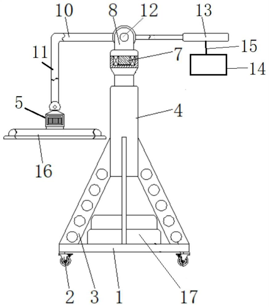
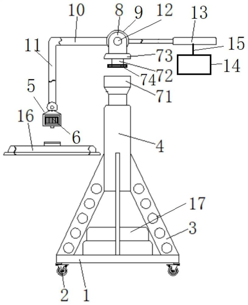
[0026] The following will clearly and completely describe the technical solutions in the embodiments of the present invention in combination with the embodiments of the present invention. Obviously, the described embodiments are only some of the embodiments of the present invention, not all of them. Based on the embodiments of the present invention, all other embodiments obtained by persons of ordinary skill in the art without creative efforts fall within the protection scope of the present invention.

[0027] It should be noted that, in the case of no conflict, the embodiments of the present invention and the features in the embodiments can be combined with each other.

[0028] The present invention will be further described below in conjunction with specific examples, but not as a limitation of the present invention.

[0029] The invention discloses a road engineering concrete vibrating device, such as figure 1 and figure 2 As shown, it includes a support frame, a rotatin...


PUM


Abstract

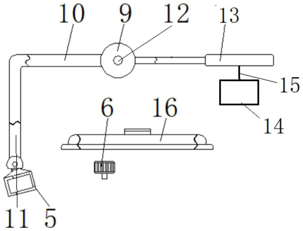
The invention provides a road engineering concrete vibrating device. The device is characterized by comprising a supporting frame, a rotating support, a hinge seat and a vibrating mechanism; a plurality of trundles are arranged on the bottom surface of the supporting frame, and the supporting frame is arranged on the ground through the trundles; the rotating support is connected with the supporting frame through a supporting column, the rotating support comprises a base, a rotating shaft and a support cover, the rotating shaft is rotationally arranged in the base, one end of the rotating shaft is limited in the base through the support cover, and the other end of the rotating shaft extends out of the support cover; the hinge seat is fixed at the other end of the rotating shaft; and the vibrating mechanism comprises a vibrating rod hinged to the hinge seat, a connecting rod perpendicularly connected with the vibrating rod and a vibrating table arranged at the end, away from the vibrating rod, of the connecting rod. The device is simple in structure and convenient to move, a constructor can be prevented from directly holding the vibration rod for operation, and the constructor is protected.

Description

technical field [0001] The invention belongs to the technical field of road construction, and in particular relates to a concrete vibrating device for road engineering. Background technique [0002] In road engineering, it is necessary to use a vibrating device to vibrate concrete, but the current vibrating device requires the operator to move the device frequently, so that other areas can be vibrated, which is extremely laborious and increases the labor intensity of the operator, and When vibrating a large area of ​​concrete, the small vibrating device can only vibrate the concrete near the edge, and the concrete near the central area needs to use large-scale equipment with extended hydraulic arms, which is extremely inconvenient. Contents of the invention [0003] The purpose of the present invention is to provide a road engineering concrete vibrating device for the deficiencies of the prior art. operate. [0004] In order to solve the problems of the technologies desc...

Claims


Application Information

Patent Timeline
Patent Type & Authority Applications(China)
IPC IPC(8): E01C19/38
CPCE01C19/38
Inventor 吕浩谭斌李建华黄威
Owner CHINA FIRST METALLURGICAL GROUP
Learn More