
Horizontal moving mechanism of three-dimensional movement photographic equipment support

A technology for photographic equipment and horizontal movement. It is applied in the direction of machine/stand, supporting machine, mechanical equipment, etc., which can solve the problems of inability to quickly reverse movement, cumbersome operation, and reduced shooting effect.

Active Publication Date: 2021-07-30
GUANGZHOU ACADEMY OF FINE ARTS
View PDF7 Cites 0 Cited by
  • Summary
  • Abstract
  • Description
  • Claims
  • Application Information

AI Technical Summary

Problems solved by technology

[0003] 1. There is only one driving mechanism in one direction, so that the camera fixed on it can only track and shoot in a single direction. Reverse displacement, in the process of sports photography can not quickly reverse movement, reducing the shooting efficiency;
[0004] 2. Many horizontal movement mechanisms used for sports photography equipment brackets fix the photography equipment brackets by means of limit bolts, which is cumbersome to operate, and the rigid connection of the bolts cannot effectively buffer the force generated during the shooting process. resulting in damage to the bolt fastening;
[0005] 3. Without a buffer device, no matter whether it is the movement generated by the device itself or the external effect, it cannot be effectively buffered, resulting in blurred shooting pictures and reducing the shooting effect

Method used


Image

  • Horizontal moving mechanism of three-dimensional movement photographic equipment support
  • Horizontal moving mechanism of three-dimensional movement photographic equipment support
  • Horizontal moving mechanism of three-dimensional movement photographic equipment support

Examples


Embodiment Construction

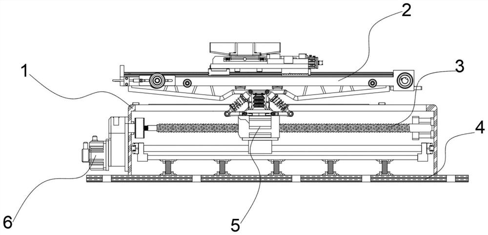
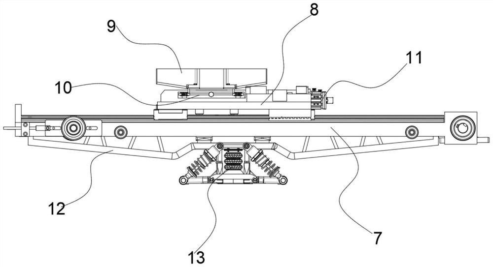
[0037] see figure 1 , in an embodiment of the present invention, a horizontal movement mechanism for a three-dimensional motion photography equipment bracket, which includes a protective housing 1, a secondary displacement assembly 2, and a threaded rod 3, wherein the threaded rod 3 is mounted on the protective housing for lateral rotation 1, and the left end of the threaded rod 3 is driven and rotated by a stepper motor 6 fixed on the outside of the protective shell 1, the threaded rod 3 is threaded and engaged by a threaded sleeve 5, and the threaded sleeve The lower end of the tube 5 is slidably connected with the limit rod fixed in the protective shell 1; the secondary displacement assembly 2 is arranged above the threaded sleeve 5; the lower end of the protective shell 1 is provided with a positioning plate 4, and , the positioning plate 4 is provided with a plurality of threaded holes for fixing the device;

[0038] A cushioning device 13 is also provided between the se...


PUM


Abstract

The invention discloses a horizontal moving mechanism of a three-dimensional movement photographic equipment support. The horizontal moving mechanism comprises a protective shell, a second-stage displacement assembly and a threaded rod, wherein the threaded rod is transversely and rotationally installed on the upper portion of the protective shell, the left end of the threaded rod is driven by a stepping motor fixed to the outer side of the protective shell to rotate, the threaded rod is engaged with a threaded sleeve through threads, and the lower end of the threaded sleeve is slidably connected with a limiting rod fixed in the protective shell; the second-stage displacement assembly is arranged above the threaded sleeve; a positioning plate is arranged at the lower end of the protective shell, and a plurality of threaded holes are formed in the positioning plate; a cushioning device is further arranged between the second-stage displacement assembly and the threaded sleeve; and the second-stage displacement assembly comprises a pneumatic sliding rail and a movable bracket, and the movable bracket is slidably arranged on the pneumatic sliding rail so that movement of a photographic support fixed to the movable bracket can be superposition movement of two independent movements in the horizontal direction.

Description

technical field [0001] The invention belongs to the technical field of photographic equipment, and in particular relates to a horizontal movement mechanism for a three-dimensional motion photographic equipment bracket. Background technique [0002] Sports photography refers to the photography method in which the camera continues to move during shooting, in which the camera can be lifted, rotated, deflected and other movements through the camera stand to meet the shooting needs of different lenses, and the camera stand often cannot be carried out along the horizontal Therefore, when some moving targets are tracked and photographed, the horizontal movement mechanism of the photographic equipment support is needed; however, according to the investigation, the horizontal movement mechanism of the existing stereoscopic motion photography equipment support often has the following problems: [0003] 1. There is only one driving mechanism in one direction, so that the camera fixed o...

Claims


Application Information

Patent Timeline
Patent Type & Authority Applications(China)
IPC IPC(8): F16M11/04F16M11/18
CPCF16M11/04F16M11/045F16M11/18
Inventor 罗保权
Owner GUANGZHOU ACADEMY OF FINE ARTS
Learn More