Emergency lighting system capable of being automatically turned on during power failure

A technology for emergency lighting and automatic opening, which is applied to lighting devices, lighting and heating equipment, and components of lighting devices. Lighting effect, the effect of improving the efficiency of evacuation work

Active Publication Date: 2021-07-30
湖北琼安科技有限公司
View PDF9 Cites 2 Cited by
  • Summary
  • Abstract
  • Description
  • Claims
  • Application Information

AI Technical Summary

Problems solved by technology

[0003] For the emergency lighting in the emergency passageway, it is usually set at a higher position on the wall, and its irradiation direction is the horizontal irradiation direction. During the emergency evacuation process, the lighting effect on the corridor floor is poor, which affects people in the evacuation process. The ground field of view in the center is likely to cause safety hazards, and the lighting device is usually exposed to the outside. After a long time, more dust and impurities will accumulate on its surface, which will reduce its lighting effect, and the existing lighting device does not have a good protection mechanism. , easy to cause damage and cause economic loss, for this reason, the present invention proposes an emergency lighting system that is automatically turned on when the power is cut off to solve the above problems

Method used


Image

  • Emergency lighting system capable of being automatically turned on during power failure
  • Emergency lighting system capable of being automatically turned on during power failure
  • Emergency lighting system capable of being automatically turned on during power failure

Examples


Embodiment Construction

[0024] The technical solutions in the embodiments of the present invention will be clearly and completely described below. The embodiments of the present invention, and all other embodiments obtained by those of ordinary skill in the art without creative work, fall within the protection scope of the present invention.

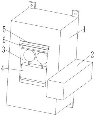
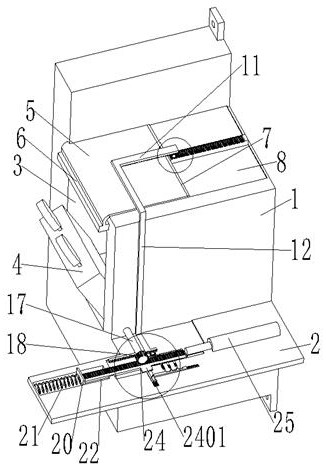
[0025] see figure see Figure 1 to Figure 6 , the present invention provides a technical solution: an emergency lighting system that is automatically turned on when a power failure occurs, the present invention includes an installation box 1, a placement box 2, an emergency lighting 4, a protective cloth 5 and a positioning auxiliary mechanism 24, an electric telescopic rod 25;

[0026] Both ends of the installation box 1 are symmetrically provided with installation feet, and one side of the installation box 1 is integrally formed with a placement box 2 , a placement slot 3 is arranged in the installation box 1, and an emergency lighting lamp is movably arrang...


PUM


Abstract

The invention discloses an emergency lighting system capable of being automatically turned on during power failure. The emergency lighting system comprises a mounting box body, a placement box, an emergency lighting lamp, protective cloth, a positioning auxiliary mechanism and an electric telescopic rod. According to the emergency lighting device capable of being automatically turned on, through cooperation among the arranged connecting rotating shaft, the arranged third transmission gear, the arranged movable rack and the arranged positioning auxiliary mechanism, the irradiation direction of the emergency lighting lamp can be made to incline downwards, then the lighting effect of the emergency lighting lamp is improved, and it is ensured that emergency evacuation work is smoothly conducted; and in addition, free stretching and retracting of the emergency lighting lamp can be achieved through the arrangement of a containing groove, protective cloth, a reset spring and an electric telescopic rod, the situation that dust and impurities adhere to the emergency lighting lamp, and the lighting effect of the emergency lighting lamp is affected can be avoided, and the emergency lighting lamp is well protected.

Description

technical field [0001] The invention relates to the technical field of emergency lighting devices, in particular to an emergency lighting system that is automatically turned on when power is cut off. Background technique [0002] Emergency lighting refers to the lighting that is activated due to the failure of the power supply of normal lighting; emergency lighting is an important safety facility for modern public buildings and industrial buildings, which is closely related to personal safety and building safety; emergency lighting is different from ordinary lighting, it includes backup There are three types of lighting, evacuation lighting, and safety lighting; the conversion time is determined according to the actual project and relevant regulations. In actual construction projects, the selection of emergency lighting power sources should be based on the number of floors, scale, complexity, stay in the building and The number of floating personnel, the characteristics of p...

Claims


Application Information

Patent Timeline
Patent Type & Authority Applications(China)
IPC IPC(8): F21S9/02F21V14/02F21V31/00
CPCF21S9/022F21V14/02F21V31/00
Inventor 邬康康
Owner 湖北琼安科技有限公司
Why Eureka
Try Eureka