
Ash bucket ash discharging device for boiler

An ash hopper and boiler technology, applied in lighting and heating equipment, etc., can solve the problems of large impact energy release, strong impact force, safety accidents, etc., and achieve the effect of improving fluidity and ensuring stability

Active Publication Date: 2021-08-06
南通宏耀锅炉辅机有限公司
View PDF9 Cites 0 Cited by
  • Summary
  • Abstract
  • Description
  • Claims
  • Application Information

AI Technical Summary

Problems solved by technology

[0004] 1. During the use of the above invention, when the ash accumulation reaches the capacity of the ash hopper, the ash accumulation cannot be automatically discharged in time. It is also necessary to manually judge whether the ash hopper has reached the required discharge capacity, and then manually rotate the closing plate to realize The whole process of the discharge of the ash hopper is cumbersome, and the discharge is not timely
[0005] 2. During the use of the above invention, the discharge speed of dust particles of different weights cannot be automatically adjusted, so that the dust particles can be discharged at a stable speed. The heavier the weight of the dust particles, the faster the falling speed, and the resulting The impact release energy is greater. If the falling speed of the ash accumulation cannot be adjusted in time, when a large number of ash accumulation particles are discharged at the same time, a strong impact force will be generated, making the discharge process prone to safety accidents.

Method used


Image

  • Ash bucket ash discharging device for boiler
  • Ash bucket ash discharging device for boiler
  • Ash bucket ash discharging device for boiler

Examples


Embodiment 1

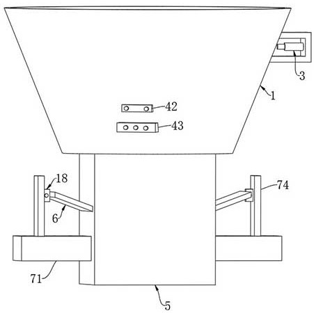
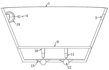
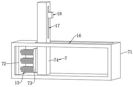
[0030] Such as Figure 1-5 As shown, an ash hopper ash-releasing device for a boiler includes an ash hopper 1, and a light-transmitting glass 2 is embedded on the side wall of the ash hopper 1, and the outer side wall of the ash hopper 1 is fixedly connected with the light-transmitting glass 2. Cooperating light pen 3, the ash hopper 1 is provided with a photosensitive mechanism 4 matched with the light pen 3, the photosensitive mechanism 4 includes a photosensitive resistor 41, an electromagnetic relay 42 and a power-off delay relay 43, and the photosensitive resistor 41 is arranged on the ash hopper 1 , and the photoresistor 41 is arranged opposite to the light pen 3, the electromagnetic relay 42 and the power-off delay relay 43 are all arranged on the outer wall of the ash hopper 1, and the photoresistor 41, the electromagnetic relay 42 and the power-off delay relay 43 The outer wall of the photoresistor 41 is provided with a transparent protective cover 19, and the transpa...


PUM


Abstract

The invention belongs to the field of ash hopper ash discharging devices, and particularly relates to an ash hopper ash discharging device for a boiler. The ash hopper ash discharging device comprises an ash hopper, light-transmitting glass is embedded on the side wall of the ash hopper, an illumination pen matched with the light-transmitting glass is fixedly connected to the outer side wall of the ash hopper, and a light sensing mechanism matched with the illumination pen is arranged on the ash hopper; and the lower end of the ash hopper is fixedly connected with a discharging pipe, and the two sides of the discharging pipe are connected with obliquely-arranged material guiding plates in a sealed and sliding manner. According to the ash hopper ash discharging device, through cooperation of the light sensing mechanism and a telescopic regulation and control mechanism, accumulated ash can be automatically discharged when the ash hopper reaches a storage limit value; and through the arrangement of a power generation mechanism and a pushing mechanism, the material guiding length of a material guiding plate can be automatically regulated and controlled according to the change of the weight of falling accumulated ash particles, and the falling accumulated ash particles can be stably discharged at a certain speed, so that the safety of discharging is ensured.

Description

technical field [0001] The invention belongs to the field of ash hopper ash discharge devices, in particular to an ash hopper ash discharge device for boilers. Background technique [0002] Existing patent (notification number: CN212253713U), a kind of ash hopper ash release device, including: ash hopper body; transition part, one end of the transition part is connected to the ash hopper body, the other end is connected to the extension pipe, and the transition pipe has a first channel , the connecting shaft is arranged on the inner wall of the transition pipe, and is rotatably connected to the transition pipe, the closing plate is arranged in the transition pipe, one end of the closing plate is rotatably connected to the connecting shaft, and the other end extends towards the inner wall of the transition pipe, and is used to close the first A channel, the counterweight component is fixedly connected to the closing plate; a cover component, one end of the cover component is ...

Claims


Application Information

Patent Timeline
Patent Type & Authority Applications(China)
IPC IPC(8): F23J1/06
CPCF23J1/06F23J2700/001
Inventor 吴洋
Owner 南通宏耀锅炉辅机有限公司
Learn More