Camera lens group

A camera lens and lens technology, applied in the field of camera lens groups, can solve the problems of increasing display processing and storage costs, increasing lens costs and installation costs, and achieve the effect of realizing large-scale clear imaging

Pending Publication Date: 2021-08-06
ZHEJIANG SUNNY OPTICAL CO LTD
View PDF0 Cites 1 Cited by
  • Summary
  • Abstract
  • Description
  • Claims
  • Application Information

AI Technical Summary

Problems solved by technology

Generally, a larger monitoring area requires several more cameras to monitor a larger area, which undoubtedly increases the cost of the lens and installation cost, and also increases the cost of display processing and storage at the back end

Method used


Image

  • Camera lens group
  • Camera lens group
  • Camera lens group

Examples


specific Embodiment 1

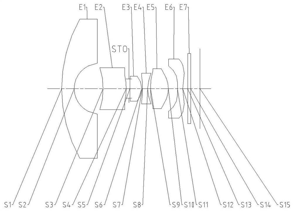
[0116] figure 1 It is a schematic diagram of the structure of the lens group of Embodiment 1 of the camera lens group of the present invention. The camera lens group includes sequentially arranged along the optical axis from the object side to the image side: the first lens E1, the second lens E2, the diaphragm STO, the second lens Three lenses E3, a fourth lens E4, a fifth lens E5, a sixth lens E6, a filter E7 and an imaging surface S15. in:

[0117] The first lens E1 has negative refractive power, its object side S1 is convex, and its image side S2 is concave; the second lens E2 has positive refractive power, its object side S3 is concave, and its image side S4 is convex; the third lens E3 has Positive refractive power, the object side S5 is convex, and the image side S6 is convex; the fourth lens E4 has negative refractive power, the object side S7 is convex, and the image side S8 is concave; the fifth lens E5 has positive refractive power, its The object side S9 is conve...

Embodiment 1

[0125] The camera lens group in embodiment 1 satisfies:

[0126] 5×tan(FOV-90°) / TTL=1.17(mm -1 ), wherein, FOV is the maximum field of view of the camera lens group, and TTL is the axial distance from the first lens object side to the camera lens composition image plane;

[0127] (DT11-DT12) / DT12=1.74, wherein, DT11 is the maximum effective radius of the object side of the first lens, and DT12 is the maximum effective radius of the image side of the first lens;

[0128] f3 / f=1.17, wherein, f3 is the effective focal length of the third lens, and f is the effective focal length of the camera lens group;

[0129] R1 / R10=-5.30, wherein, R1 is the radius of curvature of the object side of the first lens, and R10 is the radius of curvature of the image side of the fifth lens;

[0130] T45 / T56=0.32, where T45 is the on-axis distance from the fourth lens to the fifth lens, and T56 is the on-axis distance from the fifth lens to the sixth lens;

[0131] T56 / BFL=0.53, wherein, T56 is ...

specific Embodiment 2

[0156] figure 2 It is a schematic diagram of the structure of the lens group of Embodiment 2 of the camera lens group of the present invention. The camera lens group includes sequentially arranged along the optical axis from the object side to the image side: the first lens E1, the second lens E2, the diaphragm STO, the second lens Three lenses E3, a fourth lens E4, a fifth lens E5, a sixth lens E6, a filter E7 and an imaging surface S15. in:

[0157] The first lens E1 has negative refractive power, its object side S1 is convex, and its image side S2 is concave; the second lens E2 has positive refractive power, its object side S3 is concave, and its image side S4 is convex; the third lens E3 has Positive refractive power, the object side S5 is convex, and the image side S6 is convex; the fourth lens E4 has negative refractive power, the object side S7 is convex, and the image side S8 is concave; the fifth lens E5 has positive refractive power, its The object side S9 is conv...


PUM


Abstract

The invention relates to a camera lens group, and the lens group comprises a first lens, a second lens, a third lens, a fourth lens, a fifth lens, a sixth lens and a seventh lens which are sequentially arranged from the object side to the image side along an optical axis, the image side surface of the second lens is a convex surface, and the second lens has focal power; the image side surface of the third lens is a convex surface, and the third lens has positive focal power; the fourth lens has negative focal power; the image side surface of the fifth lens is a convex surface; the sixth lens has focal power; and the maximum field angle FOV of the pick-up lens group and the distance TTL from the object side surface of the first lens to the imaging surface of the pick-up lens group on the optical axis meet the condition that 5*tan(FOV-90 degrees)/TTL is greater than 0.8 mm <-1>. The pick-up lens group adopting the structure can realize large-range clear imaging, has the characteristics of ultra-thinness and miniaturization, and has important application in the fields of vehicle-mounted, security monitoring and the like.

Description

technical field [0001] The invention relates to the field of optical imaging, in particular to a camera lens, in particular to a camera lens group consisting of six lenses. Background technique [0002] With the development of optical lens technology, conventional wide-angle lenses will have dead spots in monitoring when they are applied to security and vehicles due to the limitation of the field of view of the lens. The field of view of the vehicle lens in the prior art is generally about 70°-90°, while the field of view of the security monitoring lens is generally about 90°-120°. Generally, a larger monitoring area requires several more cameras to monitor a larger area, which undoubtedly increases the cost of the lens and installation cost, and also increases the cost of display processing and storage at the back end. Contents of the invention [0003] The present invention aims to provide a camera lens group composed of six lenses. The camera lens group is a lens group...

Claims


Application Information

Patent Timeline
Patent Type & Authority Applications(China)
IPC IPC(8): G02B13/00G02B13/06G02B13/18
CPCG02B13/0045G02B13/06G02B13/18
Inventor 方铮吕赛锋姚嘉诚戴付建赵烈烽
Owner ZHEJIANG SUNNY OPTICAL CO LTD
Why Eureka
Try Eureka