
A robotic arm obstacle avoidance method based on proximity perception

A robotic arm and proximity sensor technology, applied in the field of robotic arm obstacle avoidance path planning, can solve the problems of large amount of visual information data, high price of visual sensors, and easy occlusion, so as to avoid easy occlusion, low cost, and meet real-time requirements. sexual effect

Active Publication Date: 2022-04-22
SHANGHAI UNIV
View PDF17 Cites 0 Cited by
  • Summary
  • Abstract
  • Description
  • Claims
  • Application Information

AI Technical Summary

Problems solved by technology

The main problems are: 1) The price of the visual sensor is relatively high; 2) It needs to be arranged in a suitable position, which is prone to occlusion; 3) The amount of visual information data is large, and a reasonable visual processing algorithm is required to ensure real-time control

Method used


Image

  • A robotic arm obstacle avoidance method based on proximity perception
  • A robotic arm obstacle avoidance method based on proximity perception
  • A robotic arm obstacle avoidance method based on proximity perception

Examples


Embodiment 1

[0035] A method for avoiding obstacles of a mechanical arm based on proximity perception, the specific steps are as follows:

[0036] Step 1, lay out the proximity sensor array:

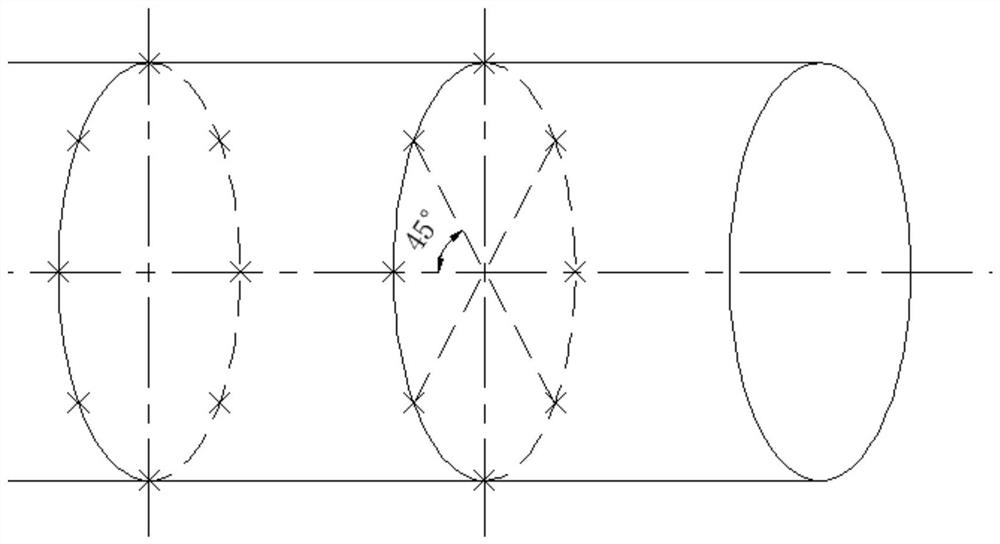
[0037] like figure 2 As shown, the proximity sensor array is arranged on the obstacle-avoiding link, and 8 (or 4, 6, etc.) are arranged equally on a circle, and each different circle is equally spaced from each other.

[0038] Step 2, determine the direction of movement of the connecting rod:

[0039] Calculate the expected pose of the connecting rod in the next control cycle through robot kinematics, combined with the current pose of the connecting rod, you can find the expected pose of the cycle under the center line of the connecting rod and determine its motion direction;

[0040] Step 3, collect sensor distance information:

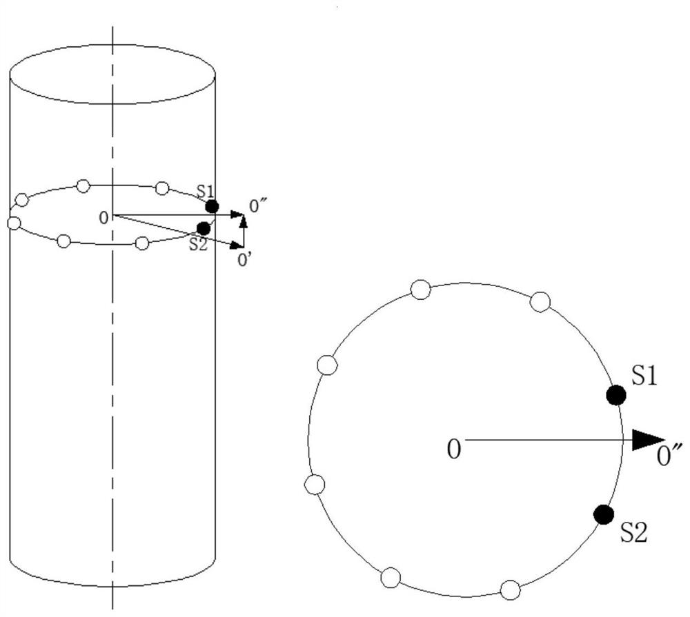
[0041] like image 3 As shown in the figure, the proximity sensor on a circle of the obstacle avoidance link is shown, O' is the desired spatial position of the center...

Embodiment 2

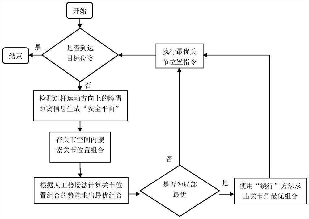
[0050] This embodiment is basically the same as Embodiment 1, and the special feature is that in step 6, the artificial potential field method often falls into the local optimal trap, but the proposed algorithm can only perceive the safe plane, and the usual artificial potential field improvement method It is difficult to apply at this time, so an improved strategy based on detour is proposed, such as Figure 7 As shown, the obstacle avoidance link escapes from the local optimal trap after using the detour strategy. In this method, when the obstacle avoidance link falls into the local optimal trap, the potential function of the gravitational field changes, making the The connected previous joint rotates in one direction, and the gravitational potential field of the other joints is still determined according to the target pose, resulting in circumvention behavior until the safe plane changes, the algorithm escapes from the local optimal trap, and finally the robot reaches the ta...


PUM


Abstract

The invention discloses a method for obstacle avoidance of a mechanical arm based on proximity perception, which adopts a proximity sensor array to perceive the spatial information of obstacles, and assumes that the surface of the obstacle is smooth, continuous and closed; the obstacle avoidance link is simplified using a cylindrical bounding box, and defined For the "direction" of its movement in space, only the sensor data in this "direction" is read in one control cycle to ensure real-time performance. Based on the data of adjacent sensors, the nearest obstacle surface is established as a cone with a certain vertex angle, and a "safety plane" is proposed to replace the obstacle based on this point. The artificial potential field method is used to plan the obstacle avoidance path of the manipulator, and a "detour" strategy is proposed to make the manipulator escape from the local optimal trap of the artificial potential field method.

Description

technical field [0001] The invention belongs to the field of obstacle avoidance path planning of a manipulator, more specifically, an obstacle avoidance method of a manipulator based on proximity perception. Background technique [0002] With the development of science and technology, robot technology is becoming more and more mature, and more and more people are involved in automated production, assembly and other work, liberating workers from repetitive and boring simple labor. On the automobile assembly line, the mechanical arm can complete welding, spraying, assembly and other work; in the logistics industry, high-speed parallel robots can accurately and efficiently complete the sorting of products; in daily households, various mobile robots can automatically clean the room , and even charge itself. In addition to the above, robot technology is also widely used in medical, military and other fields, which greatly improves the efficiency of the application field. Howeve...

Claims


Application Information

Patent Timeline
Patent Type & Authority Patents(China)
IPC IPC(8): B25J9/16
CPCB25J9/1666
Inventor 李龙陈禾炜张泉田应仲
Owner SHANGHAI UNIV
Learn More