Disinfection device for hematology department instruments

A technology for disinfection devices and equipment, applied in disinfection, water supply devices, sanitary equipment for toilets, etc., can solve the problems of incomplete disinfection and danger, and achieve the effect of complete disinfection and safety.

Active Publication Date: 2021-08-13
南京龙旺科技有限公司
View PDF16 Cites 2 Cited by
  • Summary
  • Abstract
  • Description
  • Claims
  • Application Information

AI Technical Summary

Problems solved by technology

[0006] In order to overcome the above-mentioned method, it is necessary to manually directly touch the disinfectant to take out the instrument during operation, which has certain dangers, and it is directly soaked in the disinfectant during operation, and the disinfection is not complete enough. The technical problem to be solved by the present invention is Provide a disinfection device for hematological instruments that can ensure the safety of users during operation and achieve better disinfection effects

Method used


Image

  • Disinfection device for hematology department instruments
  • Disinfection device for hematology department instruments
  • Disinfection device for hematology department instruments

Examples


Embodiment 1

[0030] A device for disinfecting blood instruments, such as Figure 1-3 As shown, it includes a base 1, a housing 2, a first guide rail 3, a slide rail 4, a telescopic rod 5, a first spring 6, a placement frame 7, a filter screen 8 and a discharge mechanism 9, and between the top of the base 1 on both sides The casing 2 is connected, the left and right sides of the casing 2 are connected with the first guide rail 3, the first guide rail 3 is slidably connected with the slide rail 4, and the sides of the slide rails 4 on both sides are connected with two Telescopic rod 5, two first springs 6 are connected in the telescopic rod 5, and placement frame 7 is connected between the bottoms of the four telescopic rods 5, and a plurality of filter screens 8 are connected on the placement frame 7, and housing 2 is provided with a placement frame 7. Material mechanism 9.

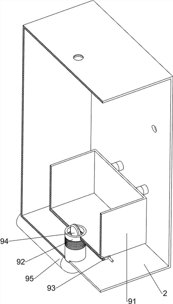
[0031] The discharge mechanism 9 includes a casing 91, a flexible pipe 92, a first rotating rod 93, a valve 94 and ...

Embodiment 2

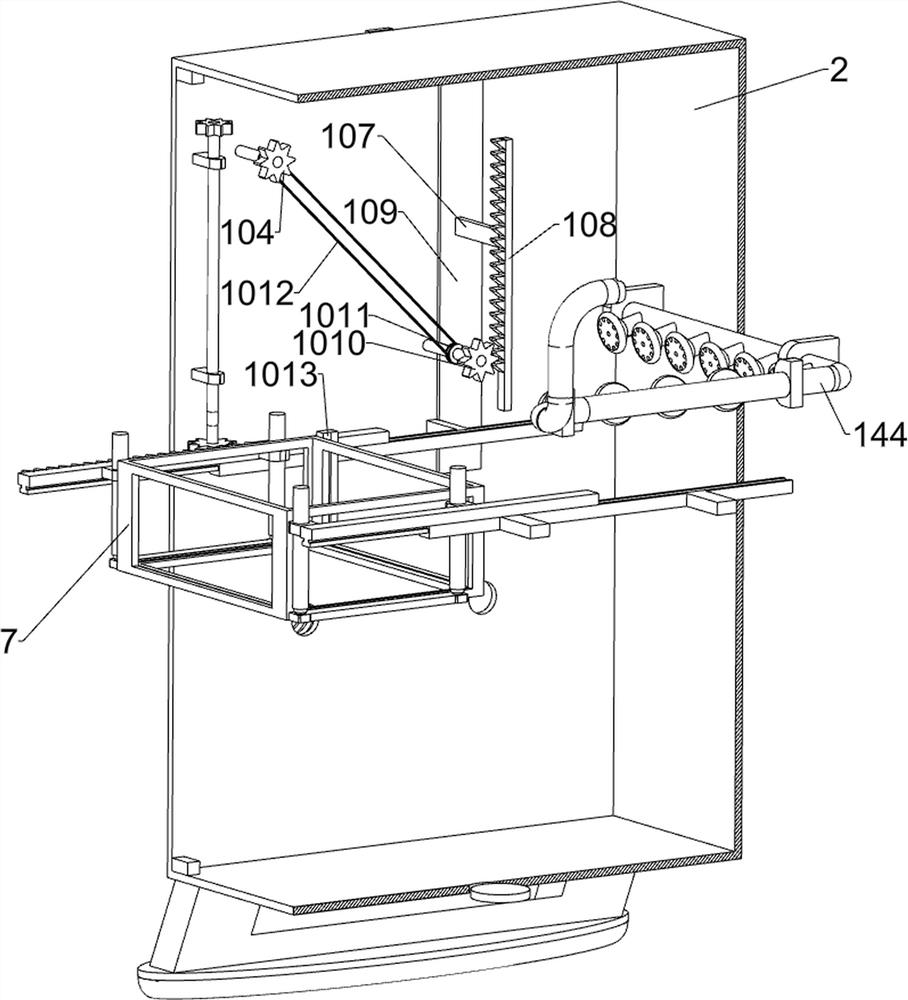
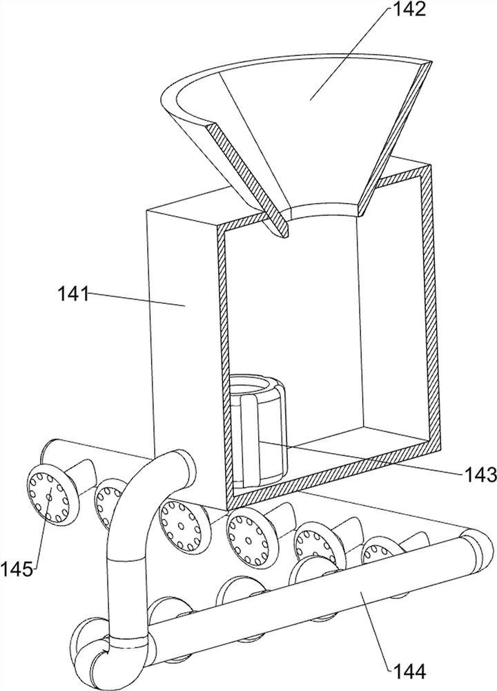
[0034] On the basis of Example 1, such as Figure 4-6As shown, it also includes a pressing mechanism 10, and the pressing mechanism 10 includes a block 101, a door panel 102, a first arc rack 103, a first gear 104, a guide rod 105, a sliding sleeve 106, a first sliding plate 107, The first tooth bar 108, the baffle plate 109, the second gear 1010, the pulley 1011, the flat belt 1112 and the fixed plate 1013, the right side of the housing 2 is rotationally connected with two blocks 101, and the two blocks 101 are connected with Door panel 102, the first arc-shaped rack 103 is connected to the door panel 102, the first gear 104 is connected to the left side of the housing 2 in a rotational manner, the first arc-shaped rack 103 will mesh with the first gear 104, and the left side of the housing 2 Two guide rods 105 are connected to the side, and a sliding sleeve 106 is slidably connected between the two guide rods 105. A first slide plate 107 is slidably connected to the slide sl...

Embodiment 3

[0040] On the basis of Example 2, such as Figure 6 As shown, a shaking mechanism 12 is also included, and the shaking mechanism 12 includes a second guide rail 121, a second slide plate 122, a contact ball 123, an elastic member 124, a contact rod 125, a wedge block 126, a second return spring 127 and a third reset Spring 128, the second guide rail 121 is connected to the left side of the housing 2, the second slide plate 122 is slidably connected on the second guide rail 121, and a plurality of contact balls 123 are evenly spaced connected on the second slide plate 122, the box body 91 and the housing 2 is connected with an elastic member 124, the left side of the box body 91 is connected with a contact rod 125, the contact rod 125 cooperates with the contact ball 123, the second slide plate 122 is connected with a wedge block 126, and the wedge block 126 cooperates with the first slide plate 107, Two second return springs 127 are connected between the first sliding plate 10...


PUM


Abstract

The invention relates to a disinfection device, in particular to a disinfection device for hematology department instruments. The disinfection device for the hematology department instruments can ensure the safety of a user during operation and has a better disinfection effect. The disinfection device for the hematology department instruments comprises bases, first guide rails, sliding rails, telescopic rods and first springs, wherein a shell is connected between the tops of the bases on the two sides; the two side walls in the shell are connected with the first guide rails; the sliding rails are connected to the first guide rails in a sliding manner; the two telescopic rods are connected to the sides, close to each other, of the sliding rails on the two sides; and the two first springs are connected into the telescopic rods. According to the disinfection device for the hematology department instruments, a discharging mechanism and a placing frame are matched to disinfect the hematology department instruments, so that the effect of disinfecting the hematology department instruments is achieved.

Description

technical field [0001] The invention relates to a disinfection device, in particular to a disinfection device for hematology instruments. Background technique [0002] The hematology department is a relatively important department in the hospital. The instruments in the hematology department usually need to be disinfected after the operation of the patient. [0003] At present, the way to sterilize the instruments of the hematology department is usually to manually throw the instruments into the disinfectant solution for disinfection, and then take out the instruments after disinfection. The direct contact of the human body with the disinfectant has certain harm and danger, and it is directly soaked in the disinfectant during operation, and the disinfection is not complete enough. [0004] Therefore, it is necessary to design a disinfection device for hematological instruments that can ensure the safety of users during operation and achieve better disinfection effects. Co...

Claims


Application Information

Patent Timeline
Patent Type & Authority Applications(China)
IPC IPC(8): A61L2/18A61L2/26
CPCA61L2/18A61L2/26A61L2202/24Y02W30/60
Inventor 邵贵林
Owner 南京龙旺科技有限公司
Why Eureka
Try Eureka