Non-static fluid pressure measuring device and using method thereof

A fluid pressure and measuring device technology, which is applied in the fields of measuring force, mechanical power, mechanical efficiency or fluid pressure, torque, stress, and work, can solve problems such as inability to measure fluid pressure more accurately, and achieve easy separation and easy observation Measurement data, the effect of quick assembly

Active Publication Date: 2021-08-13
成都辰迈科技有限公司
View PDF11 Cites 0 Cited by
  • Summary
  • Abstract
  • Description
  • Claims
  • Application Information

AI Technical Summary

Problems solved by technology

[0005] The purpose of the present invention is to solve the current problem of not being able to accurately measure the fluid pressure in the flow process

Method used


Image

  • Non-static fluid pressure measuring device and using method thereof
  • Non-static fluid pressure measuring device and using method thereof
  • Non-static fluid pressure measuring device and using method thereof

Examples


Embodiment 1

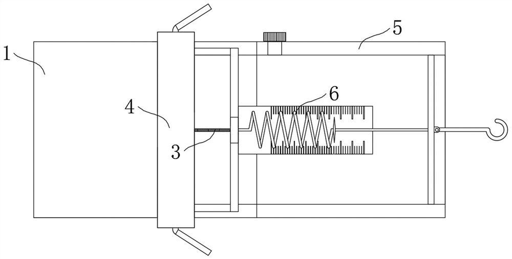
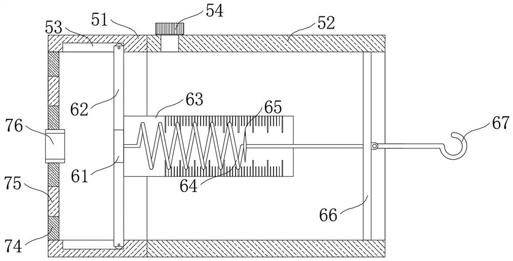
[0048] Such as figure 1 , figure 2 , image 3 , Figure 4 , Figure 5 , Figure 6 and Figure 7 As shown, this embodiment proposes a non-stationary fluid pressure measurement device, which includes a hard shell 1, and the inside of the hard shell 1 is provided with a pressure detection structure 2 and a driving mechanism 3, and the driving mechanism 3 is located on one side of the pressure detection structure 2 , the pressure detection structure 2 reflects the sensed fluid pressure through the movement of the light irradiation point, and the driving mechanism 3 operates according to the movement of the light irradiation point. One side of the hard shell 1 is provided with an observation part casing 5, and the observation part casing 5 The internal medium can be replaced according to actual needs. There is a disassembly sealing mechanism 4 between the hard casing 1 and the observation part casing 5. The disassembly sealing mechanism 4 is convenient for disassembling the h...

Embodiment 2

[0050] The scheme in embodiment 1 is further introduced below in conjunction with specific working methods, see the following description for details:

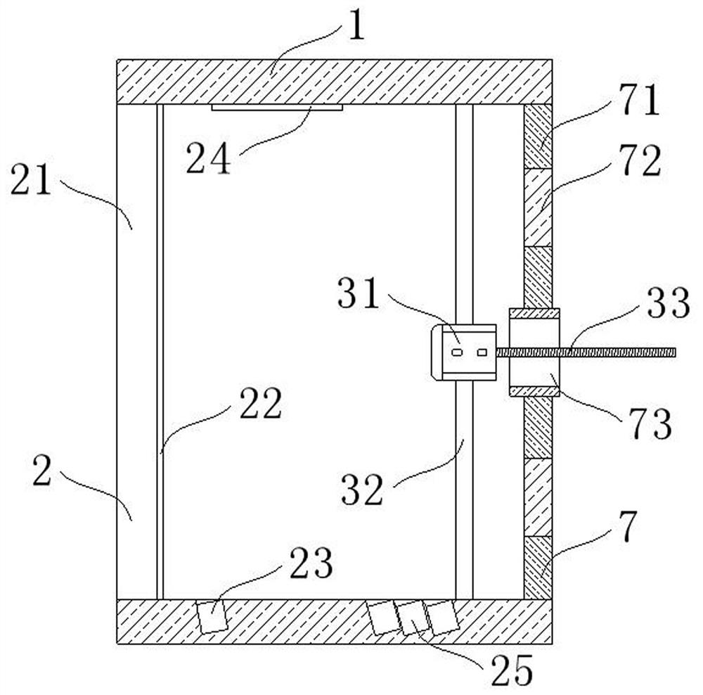
[0051] As a preferred embodiment, on the basis of the above method, further, the pressure detection structure 2 includes a thin film 21 fixedly connected to the inside of the hard shell 1 and away from the side of the drive mechanism 3, when the external pressure is greater than the internal pressure of the hard shell 1 , the thin film 21 is deformed, and the surface of the thin film 21 close to the driving mechanism 3 is coated with a reflective layer 22. When the thin film 21 is deformed, the path of the light reflected by the reflective layer 22 changes, and the inner wall of one side of the hard shell 1 is embedded with a The reflective mirror 24 reflects the light reflected by the reflective layer 22 again, and enlarges the moving distance of the light point. The other side of the hard shell 1 is embedded with a light sour...

Embodiment 3

[0061] The schemes in Embodiment 1 and Embodiment 2 are further introduced below in conjunction with specific working methods, see the following description for details:

[0062] A method for using a non-static fluid pressure measuring device, comprising the following steps:

[0063] Step 1, assemble the device: according to the actual needs, replace the observation part housing 5 and its internal structure and the internal medium of the observation part housing 5 according to the fluid pressure according to the actual needs, and the hard case 1 and the observation part can be connected by disassembling the sealing mechanism The shell 5 is separated, and the observation part shell 5 and its internal structure are replaced according to the external pressure, and then the hard shell 1 and the replaced observation part shell 5 are quickly assembled through 7;

[0064] Step 2, pressure detection: during detection, the outside of the hard shell 1 is in the fluid, and the pressure d...


PUM


Abstract

The invention provides a non-static fluid pressure measuring device and a using method thereof, and belongs to the field of measuring force, stress, torque, work, mechanical power, mechanical efficiency or fluid pressure. The non-static fluid pressure measuring device comprises a hard shell, a pressure detection structure and a driving mechanism are arranged in the hard shell, the driving mechanism is located on one side of the pressure detection structure. An observation part shell is arranged on one side of the hard shell, a detachable sealing mechanism is arranged between the hard shell and the observation part shell, and an assembling mechanism is arranged in the side, opposite to the observation part shell, of the hard shell. Through cooperative use of the driving mechanism and the data observation mechanism, the pressure received by the thin film is represented through the deformation quantity of the spring, the thin film is kept in a non-deformation state when the fluid pressure is measured, and the problem that in the prior art, after the thin film deforms due to pressure, when fluid passes through the deformed thin film, the flow velocity is changed, and the measured data of the fluid pressure is inaccurate is solved.

Description

technical field [0001] The present invention relates to the field of measuring force, stress, torque, work, mechanical power, mechanical efficiency or fluid pressure, in particular to a fluid pressure measuring device, in particular to a non-static fluid pressure measuring device and its usage method. Background technique [0002] Fluid pressure can be defined as: Considering a certain plane inside the fluid, when there is no relative motion of the fluid on both sides of the plane, the force on any unit area on the surface; from a microscopic point of view, pressure is the result of molecular motion colliding with the container wall The performance of the average force, now the fluid pressure measurement usually measures the static pressure of the fluid. [0003] The working principle of the thin-film pressure sensor is to use the deformation of the film to measure the fluid pressure. When the fluid is flowing, the fluid will be affected by the deformed film when it passes t...

Claims


Application Information

Patent Timeline
Patent Type & Authority Applications(China)
IPC IPC(8): G01L7/02G01L7/08
CPCG01L7/02G01L7/022G01L7/024G01L7/086
Inventor 庄伟
Owner 成都辰迈科技有限公司
Why Eureka
Try Eureka