Method for compensating label surface of optical disk radially

A compensation method and label surface technology, applied in the directions of record carrier accessories, instruments, packaging, etc., can solve the problems of inability to draw a uniform pattern and uneven density of pattern lines.

Inactive Publication Date: 2011-10-12
QUANTA STORAGE INC
View PDF4 Cites 0 Cited by
  • Summary
  • Abstract
  • Description
  • Claims
  • Application Information

AI Technical Summary

Problems solved by technology

[0005] However, when the label surface 18 burns the pattern, because there is no data track on the label surface 18, the address mark cannot be used to solve the problem of displacement offset, and when the line drawing of the label surface 18 is performed, the pattern lines are sparse and dense. Not uniform, unable to paint a uniform pattern
Therefore, in the background technology, there are still problems to be solved urgently on the voltage compensation of the radial displacement offset of the label surface of the optical disc.

Method used


Image

  • Method for compensating label surface of optical disk radially
  • Method for compensating label surface of optical disk radially
  • Method for compensating label surface of optical disk radially

Examples


Embodiment Construction

[0034] With regard to the technical means and effects adopted by the present invention to achieve the above-mentioned objects, preferred embodiments are described below with accompanying drawings.

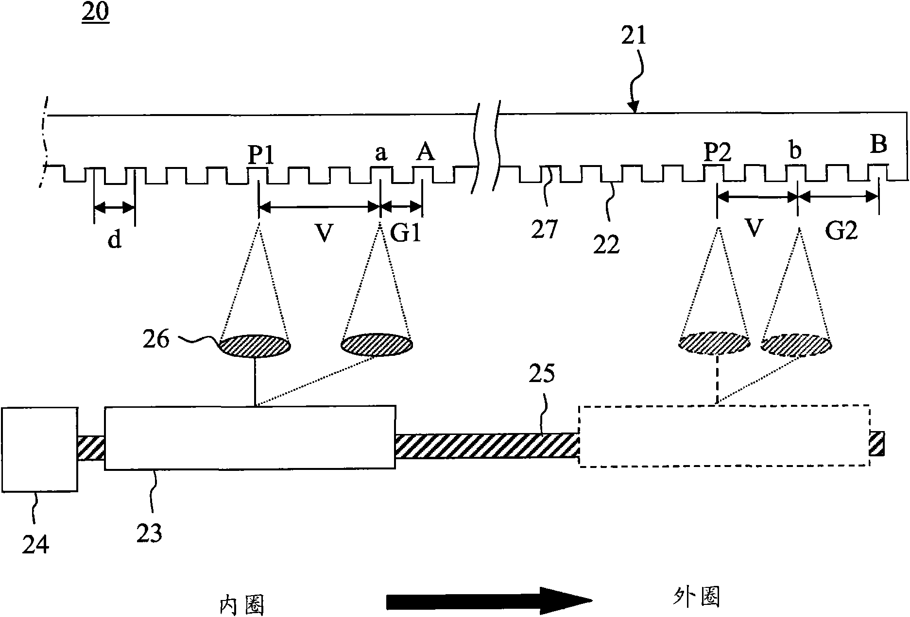
[0035] Please refer to figure 2 , Is a schematic diagram of the radial compensation method for the label surface of the optical disc according to the first embodiment of the present invention. First, put the optical disc 21 in the optical engraving machine 20 so that the data surface 22 faces the optical pickup 23. The stepping motor 24 is controlled to rotate the lead screw 25, and the coarse adjustment optical pickup 23 moves to a specific point P1 of the inner circle of the optical disc 21, and the best position of the specific point P1 is the starting point of the inner circle. The objective lens 26 is driven by the voltage V required to move to the target distance A set by the optical engraving machine 20. The actual movement distance a of the objective lens 26 can be calculated...


PUM


Abstract

The invention discloses a method for compensating a label surface of an optical disk radially. The method comprises the following steps of: putting a data surface of the optical disk into an optical disk machine; dividing the data surface into at least one compensating area; moving an optical pickup head from an inner ring to an outer ring in a simulative writing mode till the optical pickup head reaches a preset specific point; radially compensating and recording a voltage gain value; putting the label surface of the optical disk into the optical disk machine; converting a moving distance of the optical pickup head required by writing a pattern on the label surface into the number of simulative moving tracks; computing the voltage gain value required by a voltage for radially driving an object lens by using a voltage compensating formula; and moving the optical pickup head to write the label surface of the optical disk.

Description

Technical field [0001] The invention relates to a light-engraving disc machine, in particular to a method for compensating the voltage of the radial movement of an optical reading head on the label surface of the optical disc when the light-engraving disc machine burns patterns on the label surface of the optical disc. Background technique [0002] Generally, the two sides of an optical disc are a data side and a label side. The data side can use an optical pickup to record the data to be stored, and the label side can use stickers or pens to mark the contents of the optical disk. Now there is a kind of special optical disc, which is coated with special dye on the label surface, matched with a specific Light Scribe Disk Drive and burning program, can easily form a specific pattern and text on the label surface, and use it More diverse and personal. [0003] Such as figure 1 As shown, it is a schematic diagram of burning an optical disc with a light engraving machine in the backgro...

Claims


Application Information

Patent Timeline
IPC IPC(8): G11B23/40
Inventor 郭起祥赖俊文黄识忠
Owner QUANTA STORAGE INC
Why Eureka
Try Eureka