Method and apparatus of calibrating parameters of servo signals

A signal and parameter technology, applied in the parameter field of servo signals, can solve the problems of optical path deviation, reduce servo control accuracy, endanger the quality of optical drive data access, etc., and achieve the effect of improving the recording quality.

Inactive Publication Date: 2007-05-02
MEDIATEK INC
View PDF0 Cites 0 Cited by
  • Summary
  • Abstract
  • Description
  • Claims
  • Application Information

AI Technical Summary

Problems solved by technology

If the laser diode shown in Figure 1 increases the laser power, the power of the reflected laser beam also increases, which causes the optical path to shift
As shown in Figure 2, when the laser power is increased, the center of the power distribution curve is moved from C to C', this action causes the laser spot 116 shown in Figure 3 to move to the left on the photosensor 114, and the laser The movement of the light spot will have a huge impact on the tracking servo control, which will endanger the quality of data access of the optical drive
[0006] The prior art optical drive 100 cannot compensate for the above-mentioned shortcomings of reducing the accuracy of servo control, so how to provide a method that can compensate for the above-mentioned shortcomings to improve the performance of the optical drive has become one of the most important issues in the manufacture of optical drives.

Method used


Image

  • Method and apparatus of calibrating parameters of servo signals
  • Method and apparatus of calibrating parameters of servo signals
  • Method and apparatus of calibrating parameters of servo signals

Examples


Embodiment Construction

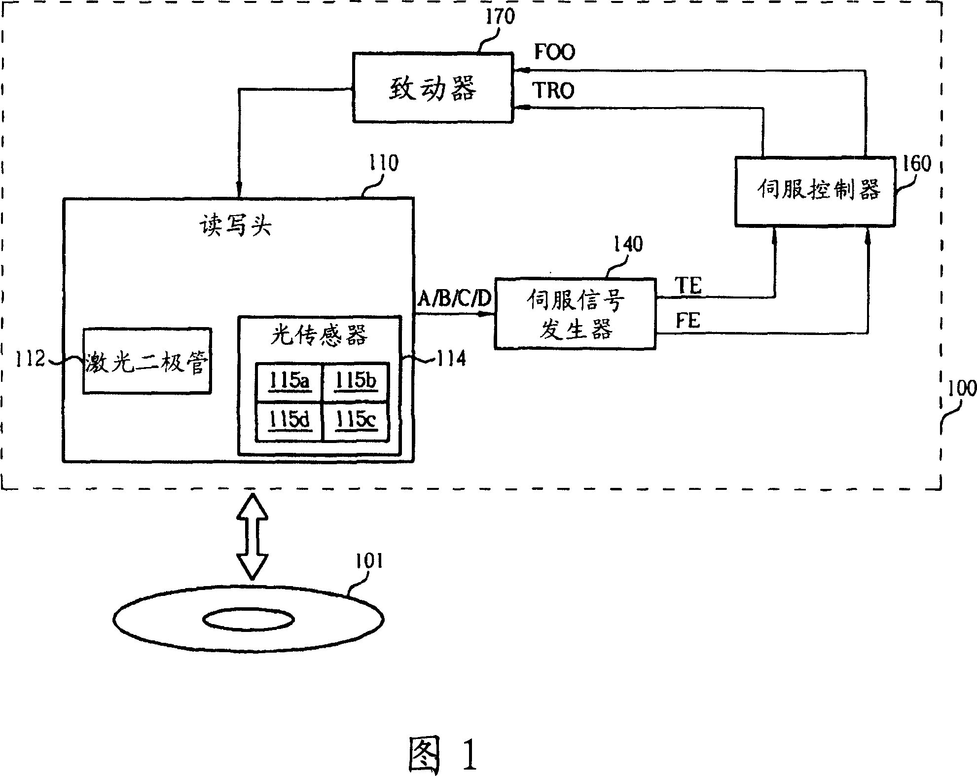
[0048] Please refer to FIG. 4 . FIG. 4 is a functional block diagram of an optical drive 400 (such as a DVD drive) according to the first embodiment of the present invention. Since the device shown in FIG. 1 has the same functions and operations as the components with the same name in the device shown in FIG. 4 , the details are not repeated here.

[0049] In this embodiment, in order to compensate the focus error signal FE, the system uses a focus error offset (FE offset) to adjust the servo control operation. For example, the servo signal generator 440 can use the synthesized detection signals A, B, C and D to generate the focus error signal FE according to the following equation:

[0050] FE=(A+C)-Kb*(B+D)+FE offset formula (1)

[0051] Please note that the Kb value in formula (1) is a parameter value used to adjust the ratio of the sum of the detection signals A and C and the sum of the detection signals B and D. In order to optimize the focus control, the parameter value ...


PUM


Abstract

A method and device for calibrating a parameter of a servo signal of an optical drive, the method includes: (a) adjusting the parameter; (b) according to a plurality of output signals from one side of an optical sensor detect the signal to generate a first signal; (c) generate a second signal according to a plurality of detection signals output by the other side of the photosensor; (d) generate a coefficient according to the first and second signals and (e) if a criterion for the coefficient value is met, then using the parameter corresponding to the coefficient value as an optimal parameter for the servo signal. The optical drive and the related servo parameter correction method of the present invention can greatly improve the burning quality and the burning efficiency of the whole system.

Description

technical field [0001] The invention provides a method and device for calibrating servo signals, especially a method and device for calibrating the parameters of a servo signal of an optical drive. Background technique [0002] Optical storage media (such as a DVD disc) are currently very common storage media. Please refer to FIG. 1 . FIG. 1 is a functional block diagram of an optical drive 100 in the prior art. The optical drive 100 (such as a DVD optical drive) has a read-write unit 110 for reading data on the optical disc 101 or burning data on the optical disc 101 . The reading and writing unit 110 includes a laser diode 112, which is used to emit a laser beam with a specific power on a track of the optical disc 101; and an optical sensor 114, which is used to detect the laser beam reflected by the optical disc 101 to generate a plurality of detection signals A, B, C and D. As known to those skilled in the art, the light sensor 114 generally has four sensing regions: ...

Claims


Application Information

Patent Timeline
Patent Type & Authority Applications(China)
IPC IPC(8): G11B7/00G11B7/09
CPCG11B7/094G11B7/0945G11B27/36
Inventor 李启瑞柯世豪陈俊壬何旭峰沈永錤
Owner MEDIATEK INC
Why Eureka
Try Eureka