
A core wire stripping tool table

A technology for stripping tools and core wires, which is used in cable installation, disassembly/armoured cable equipment, electrical components, etc. It can solve the problems of irreversibility, waste of staff time, and rough wire peeling methods, saving time. Effect

Active Publication Date: 2021-11-12
江苏海川光电新材料有限公司
View PDF0 Cites 0 Cited by
  • Summary
  • Abstract
  • Description
  • Claims
  • Application Information

AI Technical Summary

Problems solved by technology

[0005] Therefore, the technical problem to be solved by the present invention is that the traditional wire peeling method is relatively rough and irreversible, and the length of the cut cannot be guaranteed. Moreover, if it is misoperated, it is difficult to re-wrap it again, and it will cost a lot of money. large staff time

Method used


Image

  • A core wire stripping tool table
  • A core wire stripping tool table
  • A core wire stripping tool table

Examples


Embodiment 1

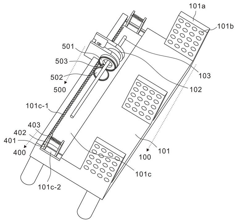
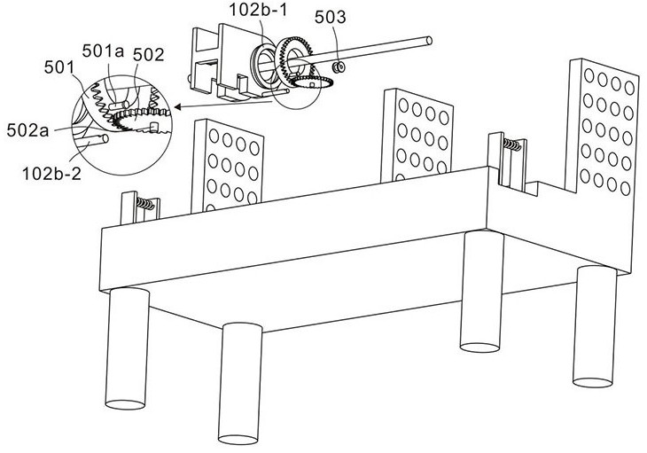
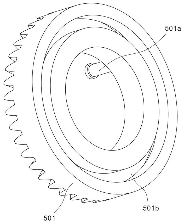
[0030] refer to Figure 1~6 , is the first embodiment of the present invention, which provides a core wire stripping tool table, which includes a processing assembly 100 and a clamping assembly 400 .

[0031] The processing assembly 100 includes a workbench 101, a cutting part 102 and a core wire 103. Specifically, a partition plate 101a is vertically arranged on the workbench 101, and a plurality of through holes 101b are arranged on the partition plate 101a, and the core wire 103 to be processed can pass through Hanging on the partition plate 101a through the through hole 101b, a guide groove 101c is arranged horizontally on the workbench 101, and the guide groove 101c is close to the edge of the workbench 101 side, and a square chute mouth is provided at the bottom of the cutting part 102, and the cutting part 102 is erected on the edge of the workbench 101 through this chute opening, the main part of the cutting part 102 is located in the guide groove 101c, and the core wi...

Embodiment 2

[0040] refer to Figure 7 , 8 , is the second embodiment of the present invention, which is based on the previous embodiment, and further includes a wire stripping assembly 200 and a control assembly 300 .

[0041] The wire stripping assembly 200 includes a second elastic member 201 and a wire stripping block 202. Specifically, a long groove 102a-1 is arranged on the upper circumference of the first through plate 102a, and the long groove 102a-1 communicates with the circular groove A, and the wire stripping block 202 is installed on In the long groove 102a-1, one end of the second elastic member 201 is fixedly connected to the back of the wire stripping block 202, and the other end is fixedly connected to the end wall of the long groove 102a-1. The end of the wire stripping block 202 facing the core wire 103 is a cutting tip. When 103 is located in the circular groove A and needs to be stripped, the cutting tip of the stripping block 202 is inserted into the core wire 103. I...


PUM


Abstract

The invention discloses a core wire stripping tool table, which includes a processing assembly, the processing assembly includes a workbench, a cutting part and a core wire, the cutting part is slidably installed on the workbench, and the core wire can be worn through and a clamping assembly, which is movably arranged at both ends of the workbench, and includes a first clamping plate, a second clamping plate and a third elastic member, the first The first clamping plate and the second clamping plate have the same structure and are arranged symmetrically, the third elastic member is located between the first clamping plate and the second clamping plate, and one end of the third elastic member is connected to the first clamping plate Hold the plate and connect the other end to the second clamping plate; the present invention can accurately strip the wires, adapt to wires of different thicknesses, and does not need to cut the outer skin in sections, and keep the complete wire outer skin, and use the insulation skin to re-wrap it later. The speed can automatically follow the moving speed to speed up or slow down, and the package is more uniform; saving more time and labor.

Description

technical field [0001] The invention relates to the technical field of wire stripping, in particular to a core wire stripping tool table. Background technique [0002] In the current digital age where electric power is developed, cables and wires play a very important role as the medium of transmission. Wires are needed in almost every industry and every enterprise, and current wire production often requires the use of various A tool strips, connects and wraps the wires, and usually a wire stripper is used in the field to strip the wires or data cables; [0003] However, wire strippers can only remove the sheath of a certain section of wire, and cannot guarantee the integrity of the wire. For some wires that require fine manipulation, too much or too little stripping will have a great impact, and the subsequent connection of wires The outer skin is very difficult, and it is difficult to find the cut of the wire. Contents of the invention [0004] The purpose of this sect...

Claims


Application Information

Patent Timeline
Patent Type & Authority Patents(China)
IPC IPC(8): H02G1/12
CPCH02G1/1251
Inventor 刘健杜刚
Owner 江苏海川光电新材料有限公司
Learn More