Dust fall type automatic punching device for carton packaging material production

A technology of packaging materials and punching equipment, which is applied in metal processing, separation of dispersed particles, chemical instruments and methods, etc., can solve the problems of inconvenient dust treatment, etc., and achieve the effect of simple structure, convenient use, and enlarged suction range

Pending Publication Date: 2021-08-17
吴江市丽星包装材料有限公司
View PDF1 Cites 0 Cited by
  • Summary
  • Abstract
  • Description
  • Claims
  • Application Information

AI Technical Summary

Problems solved by technology

[0005] The purpose of the present invention is to solve the disadvantage of being inconvenient to deal with the dust, and propose a dust-reducing automatic punching equipment for the production of carton packaging materials

Method used


Image

  • Dust fall type automatic punching device for carton packaging material production
  • Dust fall type automatic punching device for carton packaging material production
  • Dust fall type automatic punching device for carton packaging material production

Examples


Embodiment 1

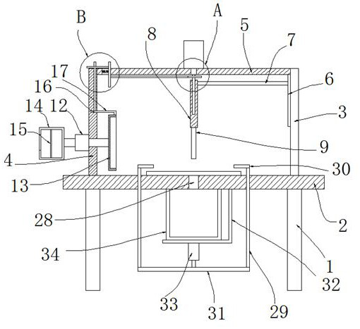
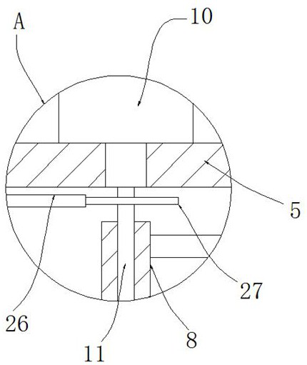
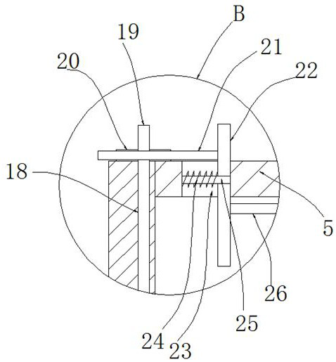
[0023] refer to Figure 1-3 , a kind of automatic punching equipment for the production of dust-reducing carton packaging materials, comprising a punching table 2, a first vertical board 3 and a second vertical board 4 are fixedly installed on the top of the punching table 2, and one of the second vertical boards 4 An air extractor 12 is fixedly installed on the side, and the air inlet of the air extractor 12 is fixedly connected with one end of an air intake hose, and the other end of the air intake hose is fixedly connected with an exhaust hood 13, and the air outlet of the air extractor 12 is fixedly connected One side is set as the filter box 14 of opening, and the filter screen 15 is fixedly installed in the filter box 14, and a side of the second vertical plate 4 is provided with a horizontal groove 16, and an L-shaped rod 17 is installed in the horizontal groove 16, and the L-shaped rod One end of 17 is fixedly connected with exhaust hood 13, offers vertical hole 18 on ...

Embodiment 2

[0030] refer to Figure 1-3 , a kind of automatic punching equipment for the production of dust-reducing carton packaging materials, including a punching table 2, the top of the punching table 2 is fixed with a first vertical board 3 and a second vertical board 4 by bolts, and the second vertical board 4 One side of the air extractor 12 is fixedly installed with bolts, and the air intake of the air extractor 12 is fixedly connected with one end of the intake hose, and the other end of the intake hose is fixedly connected with an exhaust hood 13, and the air extractor 12 The air outlet is fixedly connected with a filter box 14 with an opening on one side, and a filter screen 15 is fixedly installed in the filter box 14 by bolts, and a horizontal groove 16 is provided on one side of the second vertical plate 4, and an L-shaped Bar 17, one end of L-shaped bar 17 is fixedly connected with exhaust cover 13, offers vertical hole 18 on the top inwall of transverse groove 16, and vert...


PUM


Abstract

The invention belongs to the technical field of punching devices, and particularly relates to a dust fall type automatic punching device for carton packaging material production. Aiming at the problem that dust is inconvenient to treat when an existing punching device is used, the following technical scheme is provided: the dust fall type automatic punching device comprises a punching table, a first vertical plate and a second vertical plate are fixedly installed at the top of the punching table, an air extractor is fixedly mounted on one side of the second vertical plate, an air inlet of the air extractor is fixedly connected with one end of an air inlet hose, the other end of the air inlet hose fixedly communicates with an air extraction cover, an air outlet of the air extractor fixedly communicates with a filter box with an opening in one side, a filter screen is fixedly mounted in the filter box, a transverse groove is formed in one side of the second vertical plate, an L-shaped rod is rotationally mounted in the transverse groove, and one end of the L-shaped rod is fixedly connected with the air exhaust cover. According to the dust fall type automatic punching device, air can be sucked and filtered, dust can be removed, the structure is simple, and the use is convenient.

Description

technical field [0001] The invention relates to the technical field of punching equipment, in particular to a dust-reducing automatic punching device for the production of carton packaging materials. Background technique [0002] The production of carton packaging materials requires the use of punching equipment for punching. [0003] After searching, the patent document with the publication number: CN208962155U discloses a carton packaging material punching device. A strip-shaped groove is opened in the middle of the worktable table, and the left and right limiting platforms are respectively arranged on both sides of the strip-shaped groove. , and in the horizontal direction of the table top of the left limiting platform, there are T-shaped slots one, there are two T-shaped slots, and the two T-shaped slots are symmetrical about the axis of the left limiting platform in the horizontal direction, and on the L-shaped fixed frame The two ends of the bottom surface are respect...

Claims


Application Information

Patent Timeline
Patent Type & Authority Applications(China)
IPC IPC(8): B26F1/16B26D7/02B26D7/18B01D46/10
CPCB01D46/10B26D7/02B26D7/1863B26F1/16
Inventor 周抱根
Owner 吴江市丽星包装材料有限公司
Why Eureka
Try Eureka