Eureka AIR delivers breakthrough ideas for toughest innovation challenges, trusted by R&D personnel around the world.

Tray arranging mechanism used after rubber tube sleeving of capacitor

A technology of capacitors and rubber hoses, which is applied in the direction of capacitors, capacitor manufacturing, circuits, etc., can solve the problems of capacitor pins colliding with each other, easy to puncture defective hoses, etc., and achieve the effect of fast recognition and high recognition accuracy

Active Publication Date: 2021-08-17
NANTONG JIANGHAI CAPACITOR CO LTD
View PDF5 Cites 0 Cited by
  • Summary
  • Abstract
  • Description
  • Claims
  • Application Information

AI Technical Summary

Problems solved by technology

[0005] In order to solve the problem in the prior art that the leads of the capacitor collide with each other due to the falling of the capacitor behind the rubber hose, it is easy to puncture the rubber hose and produce defective products again, the present invention provides a disk arrangement mechanism for the capacitor behind the rubber hose

Method used


Image

  • Tray arranging mechanism used after rubber tube sleeving of capacitor
  • Tray arranging mechanism used after rubber tube sleeving of capacitor
  • Tray arranging mechanism used after rubber tube sleeving of capacitor

Examples


Embodiment 1

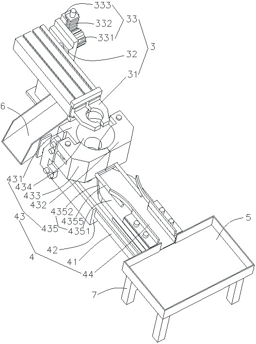
[0027] Such as Figure 3~5As shown, a disk arrangement mechanism behind a capacitor sleeve rubber hose includes a grasping device 3, a pushing device 4 and a good product disk 5 arranged in sequence; the pushing device includes a linear guide rail 41, a slider 42 and a pushing clamp assembly 43, the The push clip assembly 43 includes a clip body 431, a left clip 432 and a right clip 433, and the left clip 432 and the right clip 433 are all rotatably arranged on the clip body 431, and the clip body 431, the left clip 432 and the right chuck 433 surround and pass through a clamping cavity 434 along the circumferential direction, the clamping cavity 434 is opened in the vertical direction, and the left clamp 432 and the right clamp 433 are driven to rotate by the clamp driver 435, when When the left chuck 432 and the right chuck 433 rotate close to each other, the clamping cavity 434 closes the clamping capacitor; when the left clamp 432 and the right clamp 433 rotate away from e...


PUM


Abstract

The invention particularly relates to a tray arranging mechanism used after rubber tube sleeving of a capacitor. The tray arranging mechanism comprises a grabbing device, a pushing device and a good product tray which are arranged in sequence. The pushing device comprises a linear guide rail, a sliding block and a pushing clamp assembly, the pushing clamp assembly comprises a clamp body, a left clamping head and a right clamping head, the left clamping head and the right clamping head are rotationally arranged on the clamp body, the clamp body, the left clamping head and the right clamping head are enclosed in the circle direction and penetrate a clamping cavity in the vertical direction, and the left clamping head and the right clamping head are driven by a clamping head driving part to rotate. When the left clamping head and the right clamping head are close to each other and rotate, the clamping cavity is closed to clamp the capacitor. The sliding block is arranged on the linear guide rail and driven by the first driving piece to slide back and forth along the linear guide rail, the clamp body is fixedly arranged on the sliding block, a flat conveying groove is formed in the end, close to the good product disc, of the linear guide rail, and the two ends of the flat conveying groove communicate with the clamping cavity and the good product disc correspondingly; a defective product groove is further fixedly formed in the sliding block and is close to the grabbing device. The grabbing device is used for grabbing the capacitor and rotating the capacitor to enable the pins of the capacitor to be upwards conveyed to the pushing device.

Description

technical field [0001] The invention belongs to the technical field of capacitor manufacturing equipment, and in particular relates to a disk arrangement mechanism for capacitors covered with rubber tubes. Background technique [0002] The production process of capacitors generally includes cutting, winding, impregnation, assembly, aging, sealing, printing, casing, measurement, packaging, inspection, etc. in sequence. The casing is to put a layer of rubber tube on the outside of the aluminum shell. , The main function of the hose is insulation, and it is used to mark the parameters of the specifications and models of the product. The capacitor has been basically formed after the casing. [0003] In the production process of existing capacitors, for example, the existing patent number is 2018202868525, and the name is "A Capacitor Laminating Machine", which is specifically disclosed, such as figure 1 As shown, several disk clips 12 are evenly distributed around the axis of t...

Claims


Application Information

Patent Timeline
Patent Type & Authority Applications(China)
IPC IPC(8): H01G13/00
CPCH01G13/00
Inventor 沙剑周枢群印险峰张燕张叔琴余云国
Owner NANTONG JIANGHAI CAPACITOR CO LTD
Why Eureka
Eureka Blog
Learn More