
Valve shaft sealing structure and butterfly valve comprising same

A technology of sealing structure and valve shaft, which is applied in the direction of shaft sealing, valve casing structure, valve lift, etc., can solve the problems of valve shaft protruding, inconvenient maintenance and replacement of packing, and no valve shaft anti-protrusion structure, so as to achieve small space occupation and external The effect of compact structure and small length

Pending Publication Date: 2021-08-20
远大阀门集团有限公司
View PDF0 Cites 0 Cited by
  • Summary
  • Abstract
  • Description
  • Claims
  • Application Information

AI Technical Summary

Problems solved by technology

The disadvantage is that the driving device 1 needs to be removed when replacing the packing, which brings inconvenience to maintenance and replacement of packing
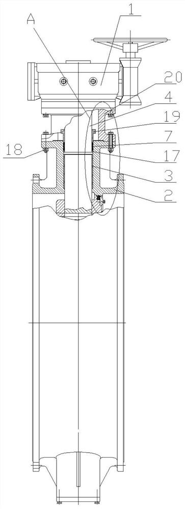
[0004] In addition, another common shortcoming of the above two prior art solutions is that there is no valve shaft anti-protrusion structure, so it is easy to make (the valve shaft breaks) after the drive device 1 is completely removed when the upper valve shaft 4 is under internal pressure. Or when the connecting pin 7 between the valve shaft and the butterfly plate is missing or fails) the valve shaft protrudes from the valve body 2, causing an accident

Method used


Image

  • Valve shaft sealing structure and butterfly valve comprising same
  • Valve shaft sealing structure and butterfly valve comprising same
  • Valve shaft sealing structure and butterfly valve comprising same

Examples


Embodiment Construction

[0033] Embodiments of the present invention will be further described in detail below in conjunction with the accompanying drawings and examples. The following examples are used to illustrate the present invention, but should not be used to limit the scope of the present invention.

[0034] In the description of the present invention, it should be noted that the terms "center", "upper", "lower", "left", "right", "vertical", "horizontal", "inner", "outer" etc. The indicated orientation or positional relationship is based on the orientation or positional relationship shown in the drawings, and is only for the convenience of describing the present invention and simplifying the description, rather than indicating or implying that the referred device or element must have a specific orientation, or in a specific orientation. construction and operation, therefore, should not be construed as limiting the invention. In addition, the terms "first", "second", and "third" are used for de...


PUM


Abstract

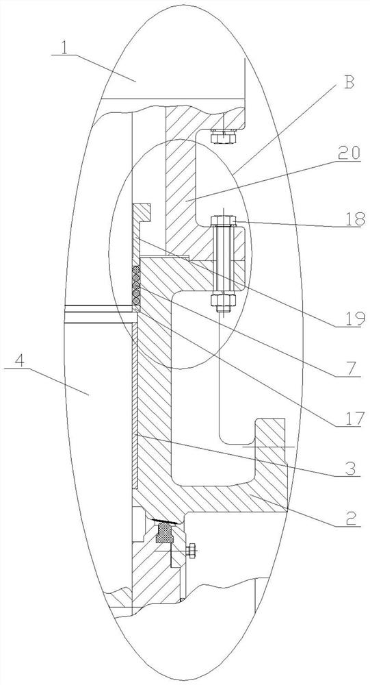
The invention discloses a valve shaft sealing structure and a butterfly valve comprising the same. The valve shaft sealing structure comprises a valve body, a driving device is installed at the upper portion of the valve body, an upper shaft hole is formed in the valve body, an upper shaft sleeve is arranged in the upper shaft hole, an upper valve shaft is arranged in the upper shaft sleeve, a stuffing box is arranged at the upper end of the upper shaft hole, and stuffings are arranged in the stuffing box. A containing groove is formed between the valve body and the driving device, a stuffing pressing plate capable of moving in the axial direction of the upper valve shaft is arranged in the containing groove, an adjusting screw rod is arranged on the stuffing pressing plate, and the adjusting screw rod penetrates through the valve body and then is in threaded connection with a first nut. The stuffing pressing plate can move up and down in the containing groove, the pressed state of the stuffings can be adjusted by rotating the first nut, and enough sealing specific pressure is obtained. The valve body is in threaded connection with a jacking screw, the upper end of the jacking screw abuts against the driving device, and the lower end of the jacking screw extends out of the valve body. The driving device can be conveniently jacked up by screwing the jacking screw, and enough open-type space for adjusting and replacing the stuffings can be conveniently obtained without dismounting the driving device.

Description

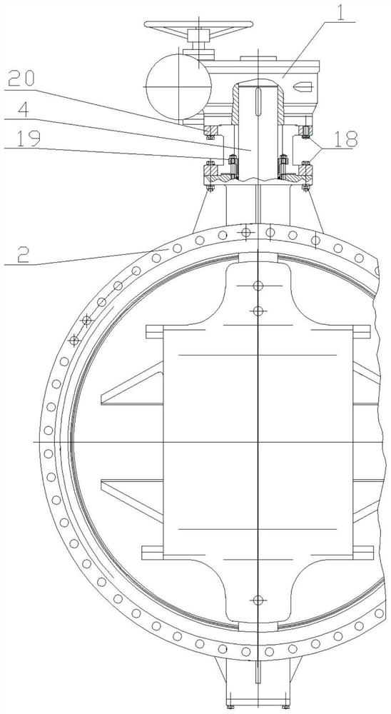
technical field [0001] The invention relates to the technical field of valves, in particular to a valve shaft sealing structure and a butterfly valve comprising the sealing structure. Background technique [0002] The extended end of the butterfly valve on which the upper valve shaft 4 extends out of the valve body 2 needs to be designed and provided with a sealing structure so that the medium will not flow out when the upper valve shaft 4 is stationary and rotates. Existing technical scheme mainly contains two kinds, prior art scheme 1 such as Figure 1-4 As shown, the stuffing box is set on the valve body 2, the stuffing gland 19 is connected to the valve body 2 by using connecting parts such as studs, and the stuffing 7, stuffing pad 17, etc. are compressed and fixed in the stuffing box, The packing 7 is elastically deformed by the packing gland 19 extrusion and limit, so a certain sealing specific pressure is established between the inner wall of the stuffing box and the...

Claims


Application Information

Patent Timeline
IPC IPC(8): F16K1/226F16K1/22F16K1/32F16K41/02F16K27/02
CPCF16K1/224F16K1/2268F16K1/32F16K27/0218F16K41/026
Inventor 李志娟张二南王瑞及进朋于国峰米红娟曹彬彬刘硕磊
Owner 远大阀门集团有限公司
Learn More