A spraying and immersion equipment for catalyst

A catalyst and equipment technology, which is applied in the field of spray dipping equipment for catalysts, can solve the problems of affecting the liquid inlet speed, many shell connection structures, and increasing the use cost of spray dipping equipment.

Active Publication Date: 2022-06-21
PINGXIANG FXSINO PETROCHEM PACKING CO LTD
View PDF7 Cites 0 Cited by
  • Summary
  • Abstract
  • Description
  • Claims
  • Application Information

AI Technical Summary

Problems solved by technology

[0003] However, the existing spraying and immersion equipment for catalysts has the following problems in application: the liquid injection port of the spraying and immersion equipment for catalysts does not use valves to control the liquid outflow, and it will not be able to stop the liquid in time. Electromagnetic valves are used to control the liquid outflow. This structure will increase the use cost of the spraying and immersion equipment used for catalysts, which does not conform to the concept of green and environmental protection development. Secondly, in order to prevent impurities in the liquid from blocking the liquid injection port, filter the impurities in the liquid in the form of a filter. A large amount of impurities will accumulate The liquid inlet is blocked, which affects the liquid inlet speed of the spraying and immersion equipment used for catalysts. Finally, there are many connection structures of the combined shells, so the weight is relatively large. Lifting part of the shell, lifting the shell will consume the physical strength of the operator, resulting in inconvenience in disassembly and assembly operations

Method used


Image

  • A spraying and immersion equipment for catalyst
  • A spraying and immersion equipment for catalyst
  • A spraying and immersion equipment for catalyst

Examples


Embodiment Construction

[0037] In order to further illustrate the various embodiments, the present invention provides accompanying drawings, which are part of the disclosure of the present invention, and are mainly used to illustrate the embodiments, and can be used in conjunction with the relevant descriptions in the specification to explain the operation principles of the embodiments. For these, those of ordinary skill in the art will understand other possible implementations and the advantages of the present invention. Components in the figures are not drawn to scale, and similar component symbols are generally used to represent similar components.

[0038] According to an embodiment of the present invention, a spray leaching apparatus for a catalyst is provided.

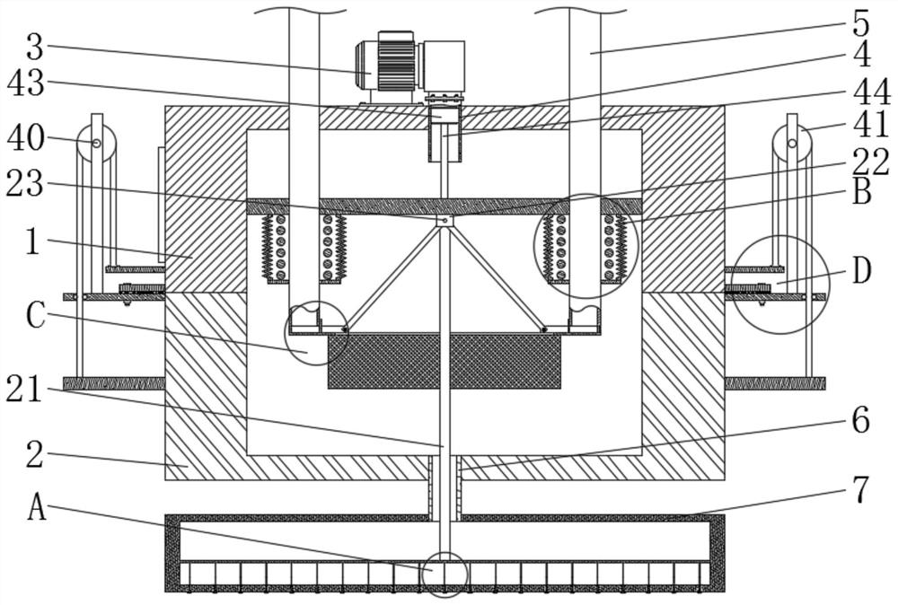
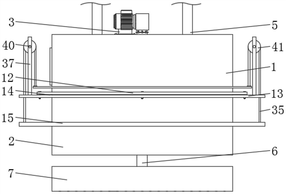
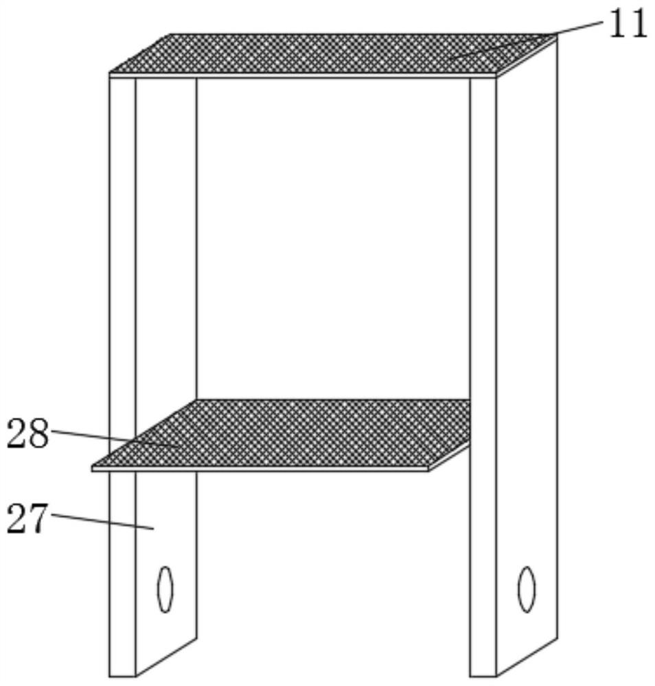
[0039] The present invention will now be further described with reference to the accompanying drawings and specific embodiments, such as Figure 1-10 As shown, a spray leaching device for catalyst according to an embodiment of the prese...


PUM


Abstract

The invention discloses a catalyst spraying and immersion equipment, which comprises an upper casing and a lower casing. The upper part of the upper casing is fixedly installed with conduits and two sets of water inlet square pipes. The upper part of the upper casing is A booster pump is fixedly installed, and one end of the booster pump is fixedly connected to the outer end of the conduit, the inner bottom surface of the lower casing is fixedly installed with a water outlet pipe, and one end of the water outlet pipe is fixedly sleeved with a water spray box , and the lower part of the water spray box is provided with several groups of fixed through holes, and the interior of several groups of said fixed through holes is installed with I-shaped tubes, and the external ends of several groups of said I-shaped tubes are all provided with adjustable sealing plates , the insides of the built-in ends of the water inlet square pipes of the two groups are all slidably installed with scraping filter screens. Beneficial effects: the present invention adjusts the sealing plate, and through the setting of the adjusting sealing plate, there is no need to add multiple sets of electromagnetic valves to control the flow of liquid ejection, and at the same time, it can stop the flow of liquid in time, so that the spraying and immersion equipment used for catalysts conforms to the concept of green and environmental protection development.

Description

technical field [0001] The invention relates to the field of louver fans, in particular to a spray dipping device for catalysts. Background technique [0002] The impregnation method is a method widely used in the industrial production of catalysts. The impregnation method is based on the impregnation of the active components (containing co-catalysts) on the porous support in the form of a salt solution and penetrates into the inner surface to form a high-efficiency catalyst. To ensure the normal use of the impregnation method, it is necessary to cooperate with the spray equipment used for the catalyst to spray its liquid, so that the liquid can be impregnated on the porous carrier and penetrate into the inner surface. The actual use of the spray equipment for the catalyst has the advantages of simple operation, permeability Good effect and stable use. [0003] However, the following problems exist in the application of the existing spray leaching equipment for catalysts: t...

Claims


Application Information

Patent Timeline
Patent Type & Authority Patents(China)
IPC IPC(8): B05B9/047B05B15/40B05B15/50B05B15/00B01J37/02
CPCB05B9/047B05B15/40B05B15/50B05B15/00B01J37/02
Inventor 徐哲
Owner PINGXIANG FXSINO PETROCHEM PACKING CO LTD
Why Eureka
Try Eureka