
A charging system and method for new energy vehicles

A new energy vehicle and charging system technology, applied in the field of new energy vehicle charging, can solve the problems of low charging efficiency, voltage fluctuation of the public power grid, affecting the safe and stable operation of the power grid, etc., to improve the utilization rate, reduce the power supply pressure, and facilitate charging services. Effect

Active Publication Date: 2022-07-08
深圳嘉信立诚科技有限公司
View PDF9 Cites 0 Cited by
  • Summary
  • Abstract
  • Description
  • Claims
  • Application Information

AI Technical Summary

Problems solved by technology

Among them, the AC charging pile is the charging pile of the conventional slow charging method. The 220V or 380V AC power supply is provided externally, and the on-board battery is charged through the on-board charger. This charging method has low installation cost and can make full use of the low power consumption time for charging. , reduce the charging cost and prolong the service life of the battery; but the charging time is too long, and there are strict requirements on the parking time and location of the electric vehicle, resulting in a decrease in its utilization efficiency
The DC charging pile is the charging of the fast charging method. The non-vehicle charger completes the AC-DC conversion, and then directly charges the vehicle battery through the dedicated DC charging interface. The charging voltage is generally 400V or 750V, which meets the needs of emergency battery life. Compared with AC charging piles, this method has low charging efficiency, high work and installation costs, and high current, which has a great impact on battery life; at the same time, high-power charging has a large impact on the power grid, and it will also cause voltage fluctuations in the public power grid and generate harmonic hazards.
[0004] With the rapid increase in the number of electric vehicles, large-scale electric vehicle charging will further increase the peak-to-valley difference rate of the power grid, causing regional power grid load fluctuations, and fluctuations in grid voltage will cause fluctuations in the output voltage of charging piles, which in turn will affect Lifespan of EV batteries
In addition, affected by various factors, the charging demand of electric vehicles has the characteristics of randomness and dispersion in time and space, which increases the difficulty of grid operation and management. Wave pollution affects the safe and stable operation of the power grid

Method used


Image

  • A charging system and method for new energy vehicles
  • A charging system and method for new energy vehicles
  • A charging system and method for new energy vehicles

Examples


Embodiment 1

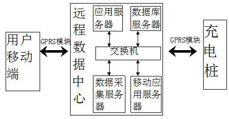
[0057] combine figure 1 , a charging system for new energy vehicles, including a scheduling unit and a charging pile, a user sends a charging request to the scheduling unit through a mobile terminal, the scheduling unit recommends charging piles for the user, and the scheduling unit provides users with a variety of charging The scheme is selected by the user.

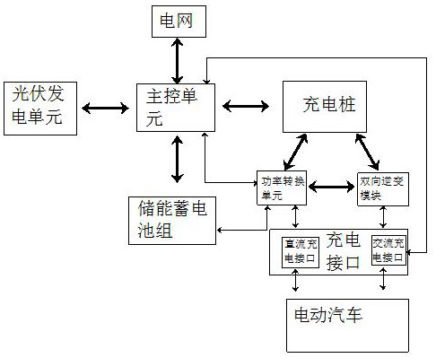
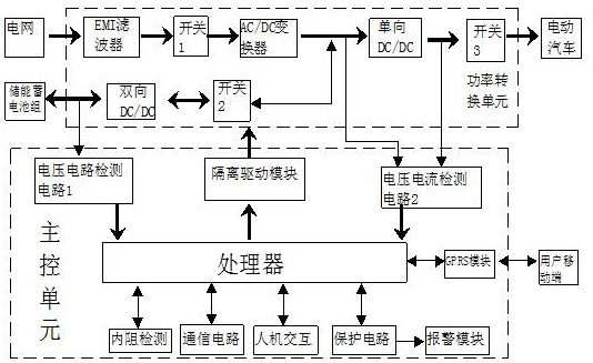
[0058] combine figure 2 , the charging pile is connected to the power grid and the photovoltaic power generation unit through the main control unit, the main control unit stores the electric energy of the photovoltaic power generation unit in the energy storage battery pack, and the photovoltaic power generation unit stores the electric energy in the energy storage battery pack When charging, the segmented charging mode is adopted, including the constant current charging stage and the constant voltage charging stage, and the battery state of charge SOC is used to measure the capacity of the energy storage battery pack...

Embodiment 2

[0063] combine Figure 4 , the protection circuit detects the fault of the charging pile, and the detection steps are as follows:

[0064] Step 1. The main control unit starts the charging pile fault detection program to determine whether the input phase is lacking, and if so, it directly cuts off the charging interface, otherwise it is included in the input overvoltage judgment;

[0065] Step 2. When the main control unit judges that the input is overvoltage, it will directly enter the delay state, and re-detect after a delay of 5s. If the voltage has been too high for three times, it will exit directly and start the alarm module display, otherwise it will enter the overcurrent judgment. ;

[0066] Step 3: When the main control unit judges that the input is over-current, it directly disconnects the charging interface, otherwise it determines whether the output is over-voltage, if it determines that the output is over-voltage, it directly disconnects the charging interface, o...

Embodiment 3

[0070] A charging method for a new energy vehicle, comprising the following steps:

[0071]S1. The user sends a charging request to the scheduling unit through the mobile terminal, and sends the remaining power of the electric vehicle. The scheduling unit recommends the appropriate charging pile and charging scheme for the user through the scheduling strategy. After the user arrives at the designated charging pile, the charging pile is selected. mode or slow charge mode;

[0072] S2. When the user selects the slow charging mode, the bidirectional inverter module of the main control unit connects the power grid to the AC end of the charging interface of the charging pile to realize slow charging. When the grid fails, the bidirectional inverter module of the main control unit will store the power grid. The low-voltage DC power of the battery pack can be converted into high-voltage AC power to supply AC power for electric vehicles and realize slow charging;

[0073] S3. When the...


PUM


Abstract

The invention relates to a charging system and method for new energy vehicles, including a dispatching unit and a charging pile, the dispatching unit recommends charging piles for users, and the charging piles are connected to the power grid and photovoltaic power generation unit through a main control unit. The main control unit stores the electric energy of the photovoltaic power generation unit in the energy storage battery pack; the charging pile is provided with a charging interface connected to the electric vehicle, and the main control unit of the charging pile realizes the charging for the electric vehicle through a bidirectional inverter module. Slow charging mode, the main control unit of the charging pile is connected to the charging interface through the power conversion unit to realize the fast charging mode for the electric vehicle, and the main control unit is unidirectionally connected to the power conversion unit through the isolation drive module; the present invention provides The charging system adopts energy storage charging piles, which are compatible with the conventional and fast charging functions of AC and DC charging piles, and through the configuration of energy storage batteries, it reduces the large amount of investment in power grid transformation and offsets the impact of a large number of charging piles on the power grid.

Description

technical field [0001] The invention belongs to the technical field of new energy vehicle charging, and in particular relates to a charging system and method for new energy vehicles. Background technique [0002] With its advantages of energy saving, zero emission, low noise, and high efficiency, electric vehicles have gradually become the focus of governments and automobile manufacturers around the world, making them the mainstream of future automobile industry development. The development of electric vehicles requires the construction of supporting charging infrastructure, including various decentralized AC and DC charging equipment, and centralized large-scale charging and swapping stations; therefore, vigorously promoting the construction of charging infrastructure is an urgent task to accelerate the promotion and application of electric vehicles. However, as a large number of electric vehicles are connected to the grid for charging without regulation and control, it may...

Claims


Application Information

Patent Timeline
Patent Type & Authority Patents(China)
IPC IPC(8): B60L53/31B60L53/51B60L53/67B60L53/68H02J3/32
CPCB60L53/31B60L53/67B60L53/68B60L53/51H02J3/32Y02T10/72Y02T90/16Y02E70/30
Inventor 李炫
Owner 深圳嘉信立诚科技有限公司
Learn More