
Stacked energy storage charging pile and charging method

A charging method and stacking technology, applied in the direction of secondary battery charging/discharging, charging station, vehicle energy storage, etc. question

Pending Publication Date: 2021-08-10
奶牛新能源(上海)有限公司
View PDF7 Cites 1 Cited by
  • Summary
  • Abstract
  • Description
  • Claims
  • Application Information

AI Technical Summary

Problems solved by technology

[0002] With the popularization of electric vehicles and the demand of electric vehicle owners for a longer range of electric vehicles, the charging parking spaces of electric vehicles will become more and more tense, causing electric vehicle owners to become more anxious about whether their charging needs can be met in time; at the same time, as The increase in the number of electric vehicles will lead to an increasing load on the grid during the charging period of electric vehicles, resulting in the possibility of being restricted by the grid; currently most of the parking spaces for electric vehicles do not have charging piles, but A certain proportion of the parking spaces with charging piles are equipped with slow charging configurations, and the charging time is long, so there is no way to meet the needs of electric vehicle owners who need to recharge in a short time
[0003] In addition, electric vehicles currently on the market use movable energy storage charging boxes for charging. These movable energy storage charging boxes are bulky, often heavy, and inconvenient to move. They need transportation tools to move to the desired location. place, which makes this type of mobile charging pile unable to be popularized
[0004] On the other hand, because the energy storage mobile charging pile is inconvenient to move, most of the energy storage mobile charging piles on the market are equipped with relatively small power, which cannot meet the power and fast charging speed required by electric vehicle owners.
[0005] In addition, if it is necessary to meet the needs of electric vehicle owners with the power and fast charging speed, it is necessary to transform the charging piles in the current parking lot, but fast charging piles are expensive and difficult

Method used


Image

  • Stacked energy storage charging pile and charging method
  • Stacked energy storage charging pile and charging method
  • Stacked energy storage charging pile and charging method

Examples


Embodiment Construction

[0034] The following description serves to disclose the present invention to enable those skilled in the art to carry out the present invention. The preferred embodiments described below are only examples, and those skilled in the art can devise other obvious variations. The basic principles of the present invention defined in the following description can be applied to other embodiments, variations, improvements, equivalents and other technical solutions without departing from the spirit and scope of the present invention.

[0035] It can be understood that the term "a" should be understood as "at least one" or "one or more", that is, in one embodiment, the number of an element can be one, while in another embodiment, the number of the element The quantity can be multiple, and the term "a" cannot be understood as a limitation on the quantity.

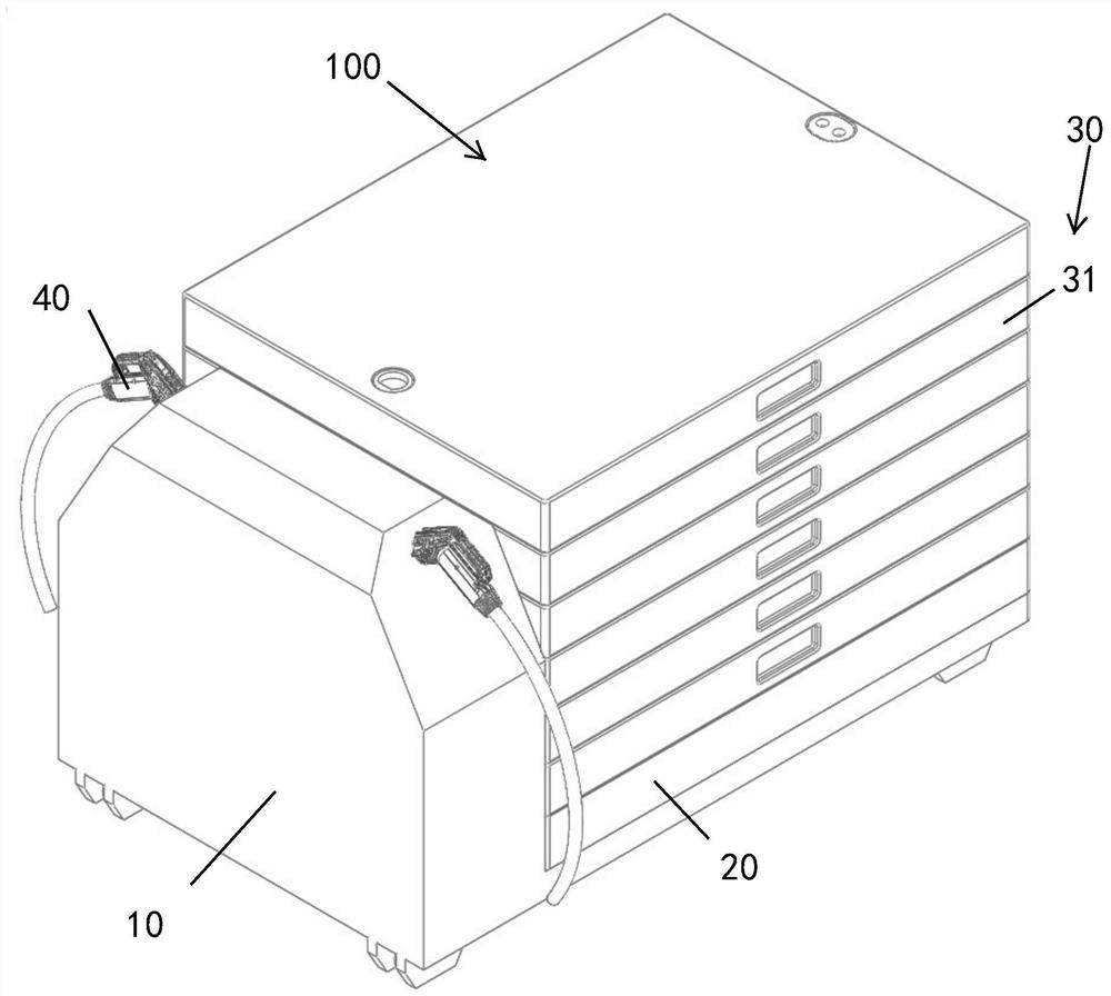
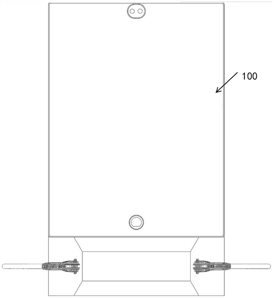
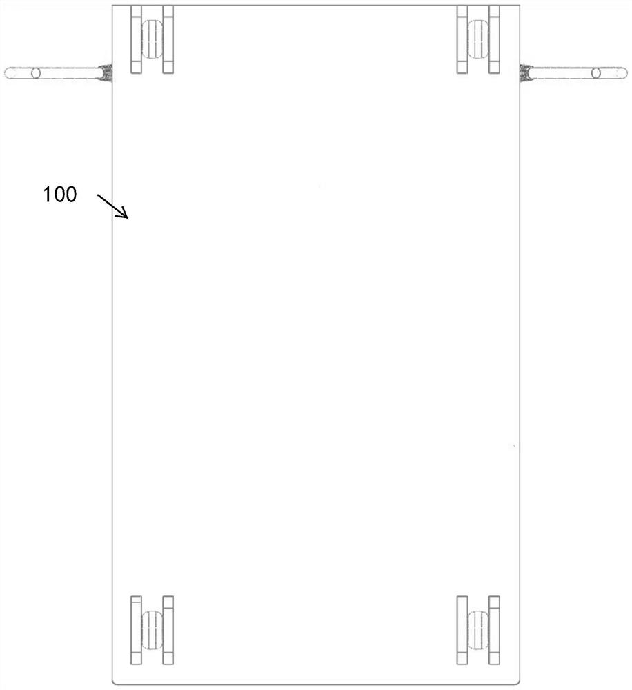
[0036] The invention provides a stacked energy storage charging pile, such as Figure 1 to Figure 7 As shown, in this preferred emb...


PUM


Abstract

The invention provides a stacked energy storage charging pile which comprises a rack, a high-voltage box and a stacking type battery standard box. The stacking type battery standard box is arranged on the high-voltage box in a stacking mode, the high-voltage box is stacked on the rack, the stacking type battery standard box comprises a plurality of standard plug-in boxes, the standard plug-in boxes are arranged in a mutually stacked manner and are mutually connected in a power and communication manner, and when one of the standard plug-in boxes of the stacking type battery standard boxes performs discharging, other standard plug-in boxes and the high-voltage box are in a disconnected state.

Description

technical field [0001] The invention relates to the field of energy storage charging, in particular to a stacked energy storage charging pile and a charging method. Background technique [0002] With the popularization of electric vehicles and the demand of electric vehicle owners for a longer range of electric vehicles, the charging parking spaces of electric vehicles will become more and more tense, causing electric vehicle owners to become more anxious about whether their charging needs can be met in time; at the same time, as The increase in the number of electric vehicles will lead to an increasing load on the grid during the charging period of electric vehicles, resulting in the possibility of being restricted by the grid; currently most of the parking spaces for electric vehicles do not have charging piles, but A certain proportion of the parking spaces with charging piles are equipped with slow charging configurations, and the charging time is relatively long. Theref...

Claims


Application Information

Patent Timeline
IPC IPC(8): B60L53/31B60L53/53B60L53/60B60L53/62H01M10/44
CPCB60L53/31B60L53/53B60L53/60B60L53/62H01M10/441Y02T10/70Y02T10/7072Y02T90/12Y02E60/10
Inventor 和学勐赵明志蒋晖宋卫荣王新凯
Owner 奶牛新能源(上海)有限公司
Learn More