Method and apparatus for adjusting height of bobbin base-plate for spinning

A technology of height adjustment and can, applied in transportation and packaging, textile and papermaking, thin material handling, etc., can solve problems such as reduced productivity of textile machines, and achieve the effects of improved quality, high productivity, and precise positioning

Inactive Publication Date: 2002-05-22
RIETER INGOLSTADT SPINNEREIMASCHENBAU AG
View PDF0 Cites 5 Cited by
  • Summary
  • Abstract
  • Description
  • Claims
  • Application Information

AI Technical Summary

Problems solved by technology

In this case, the productivity o

Method used


Image

  • Method and apparatus for adjusting height of bobbin base-plate for spinning
  • Method and apparatus for adjusting height of bobbin base-plate for spinning
  • Method and apparatus for adjusting height of bobbin base-plate for spinning

Examples


Embodiment Construction

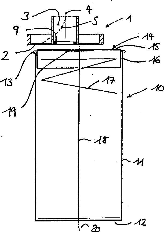
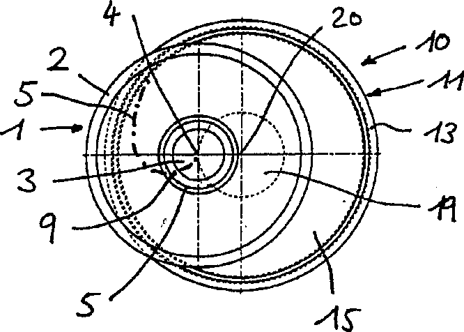
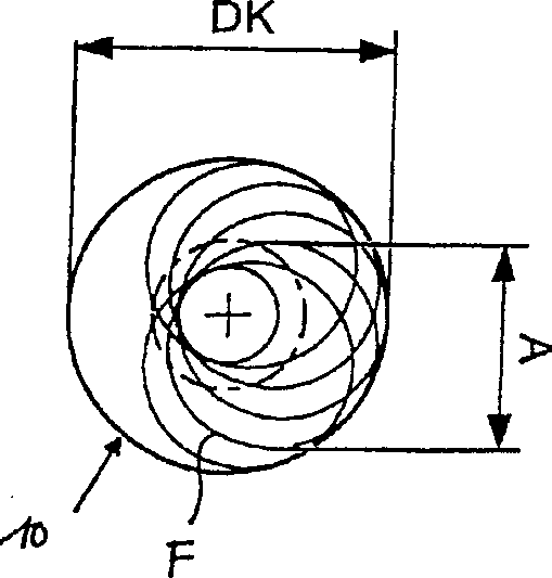
[0043] figure 1 , 2 as well as Figure 4 , 5 The outlet of the textile drafting unit and in particular the turntable 1 , the spinning package 10 or 100 to be filled located below the turntable 1 and in the filling position is schematically shown. In front of the turntable 1 at least one feed rod is drawn in the drafting unit to form a fiber sliver F of as uniform a diameter as possible and fed into the spinning package 10 , 100 by means of the turntable 1 . Commonly used spinning cylinders 10 , 100 have a circular cross section (so-called round cans) or an approximately rectangular cross section (so-called square cans). When a spinning tube 10 , 100 is filled with drawn fiber sliver, it leaves its filling position, while a subsequent spinning tube 10 , 100 is located under the turntable 1 .

[0044] In order to ensure as efficient and consistent filling of the spinning bobbins 10, 100 as possible, the turntable 1 has an open, generally circular cavity extending from a cent...


PUM


Abstract

A process for the level adjustment of the can plate 14 of a spinning can 10, 100 is proposed which is in a filling position at the output of a textile machine to be filled with fiber sliver F, whereby the can plate 14 is moved before the start of the filling process by a first moving device 17 from a lower can plate position into a higher can plate position and is moved into the lower can plate position during the filling of the spinning can 10, 100. The process according to the invention is characterized in that the can plate 14 is moved before the start or during the starting phase of the filling process by a second moving device 9, 109 from the higher can plate position into an upper filling position as the spinning can 10, 100 is in filling position. Furthermore a suitable apparatus is presented.

Description

technical field [0001] The invention relates to a method and a device for adjusting the height of the can chassis of spinning cans, said spinning cans are located at the loading position at the outlet of the textile machine for filling fiber sliver, wherein the can chassis is lifted from below by a first loading mechanism before starting to fill. The can bed position enters into the higher can bed position and moves or can be moved into the described lower can bed position when the cans are filled. Background technique [0002] Such methods and devices are known in various ways in the textile industry. In the case of spinning packages with a circular cross-section that are processed wide, the side walls of the spinning package surround at least one helical spring designed as a first loading mechanism, which presses against the can chassis from below. In the empty can state, the can chassis is ideally lifted towards its upper can edge. When filling the cans with textile mat...

Claims


Application Information

Patent Timeline
IPC IPC(8): B65H54/80B65H75/16
CPCB65H2701/31B65H75/16B65H54/80B65H2555/13
Inventor A·克里格勒F·费可
Owner RIETER INGOLSTADT SPINNEREIMASCHENBAU AG
Why Eureka
Try Eureka