High-pressure buffering air cylinder

A buffer cylinder, high-pressure technology, applied in the direction of fluid pressure actuators, valve details, engine components, etc., can solve the problems of shortened valve life, valve parts damage, no buffer function, etc., to reduce impact force and increase speed Effect

Pending Publication Date: 2021-08-27
JIANGSU SHAZHOU VALVE CO LTD
View PDF0 Cites 0 Cited by
  • Summary
  • Abstract
  • Description
  • Claims
  • Application Information

AI Technical Summary

Problems solved by technology

[0002] Although the traditional cylinder can provide a large torque in a short period of time, it does not have a buffer function. Due to its structural limit, it can only be used for small-sized valves. If it is used for large-sized valves, it will cause damage to the valve Components cause certain damage to shorten the life of the valve

Method used


Image

  • High-pressure buffering air cylinder
  • High-pressure buffering air cylinder
  • High-pressure buffering air cylinder

Examples


Embodiment Construction

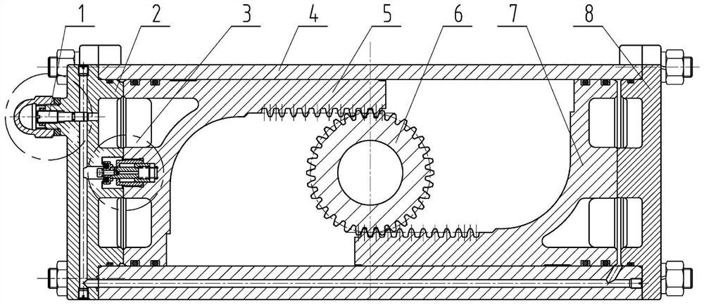
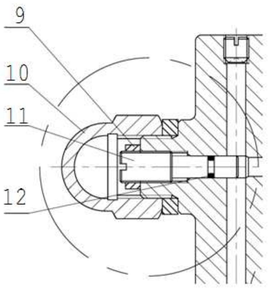
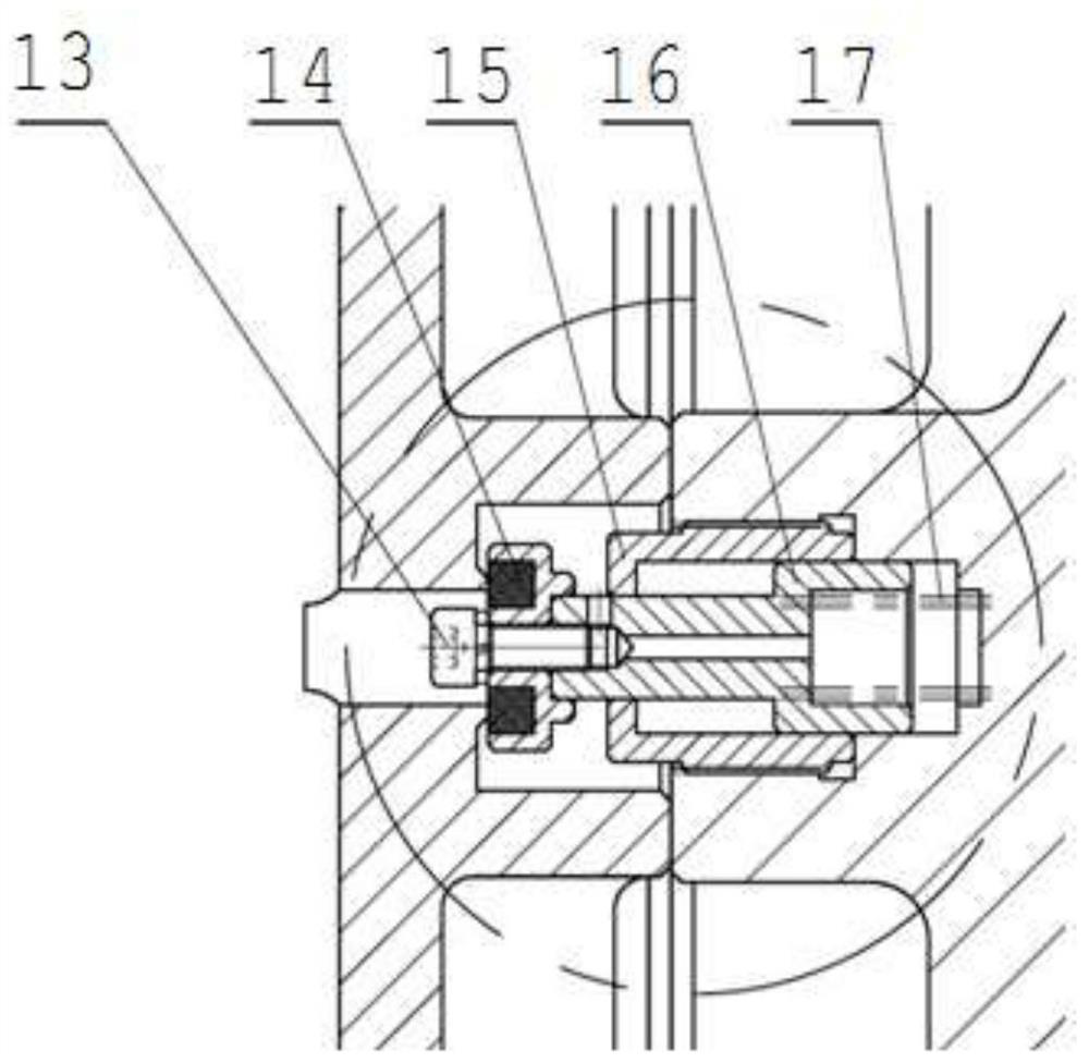
[0021] Specific embodiments of the present invention will be described in detail below with reference to the accompanying drawings.

[0022] like Figure 1-5 As shown, the high-pressure buffer cylinder includes a cylinder block 4, and the cylinder block 4 is movably provided with an inverted L-shaped left piston 5 and an L-shaped right piston 7, and the outer periphery of the left piston 5 is provided with a sealing ring matched with the cylinder block 4, The outer periphery of the right piston 7 is provided with a sealing ring that matches the cylinder 4; the end face of the left piston 5 facing the left end cover 2 is provided with an annular weight reduction groove, and the end face of the right piston 7 facing the right end cover 8 is provided with an annular weight reduction groove groove. The lower surface of the cantilever of the left piston 5 is provided with an upper driving rack, the upper surface of the cantilever of the right piston 7 is provided with a lower driv...


PUM


Abstract

The invention discloses a high-pressure buffering air cylinder. The high-pressure buffering air cylinder comprises a cylinder body, an inverted-L-shaped left piston and an L-shaped right piston are movably arranged in the cylinder body, wherein an upper driving rack is arranged on the lower surface of a cantilever of the left piston, a lower driving rack is arranged on the upper surface of a cantilever of the right piston, and a transmission gear is arranged between the cantilever of the left piston and the cantilever of the right piston; a left end cover and a right end cover are arranged at the two sides of the cylinder body, an air intake through hole is formed in the left end cover, and an air intake and exhaust port communicated with the air intake through hole and the space between the left piston and the left end cover is formed in the left end cover; an air supply through hole communicated with the air intake through hole is formed in the cylinder body, and the other end of the air supply through hole is communicated with the space between the right piston and the right end cover; and a positioning hole is formed in the middle of the end face of the left piston, a buffering guide column is movably arranged in the positioning hole, a buffering spring is arranged between the buffering guide column and the bottom of the positioning hole, a buffering block is arranged at the end of the buffering guide column, a buffering sealing gasket is arranged in the buffering block, and a positioning ring matched with the buffering sealing gasket is arranged on the left end cover.

Description

technical field [0001] The invention relates to a high-pressure buffer cylinder. Background technique [0002] Although the traditional cylinder can provide a large torque in a short time, it does not have a buffer function. Due to its structural limitations, it can only be used for small-sized valves. For example, when used on large-sized valves, it will affect the valve. Parts that cause certain damage shorten the life of the valve. SUMMARY OF THE INVENTION [0003] The technical problem to be solved by the present invention is to provide a high-pressure buffer cylinder that can provide a large torque and at the same time reduce the impact force of rapid valve opening / closing, thereby protecting valve components. [0004] In order to solve the above-mentioned technical problems, the technical scheme adopted in the present invention is as follows: a high-pressure buffer cylinder includes a cylinder block, an inverted L-shaped left piston and an L-shaped right piston are ...

Claims


Application Information

Patent Timeline
Patent Type & Authority Applications(China)
IPC IPC(8): F15B15/22F15B15/14F16K31/122F16K47/00
CPCF15B15/14F15B15/1433F15B15/149F15B15/22F16K31/1221F16K47/00
Inventor 何志刚赵力强张惠龙徐许强
Owner JIANGSU SHAZHOU VALVE CO LTD
Why Eureka
Try Eureka