Eureka AIR delivers breakthrough ideas for toughest innovation challenges, trusted by R&D personnel around the world.

Light-emitting diode lamp with residual light prevention function

A technology of light-emitting diode lamps and functions, applied in the use of semiconductor lamps, electrical components, etc., can solve the problems of light-emitting diodes 13 afterglow, etc., achieve the effect of increasing costs, solving the problem of afterglow, and simple circuit design

Pending Publication Date: 2021-08-27
XIAMEN PVTECH CO LTD
View PDF8 Cites 1 Cited by
  • Summary
  • Abstract
  • Description
  • Claims
  • Application Information

AI Technical Summary

Problems solved by technology

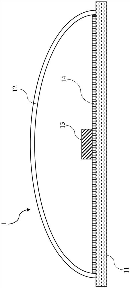
Therefore, the user will often cause the switch to cut off the zero line with no pressure difference with the ground due to wrong installation or other various reasons. Therefore, although the LED lamp 1 can be turned off, there will still be a gap between the drive circuit and the metal radiator. There is a certain amount of alternating current
[0004] A parasitic capacitance will be formed between the copper foil for the LED 13 on the circuit board 14, the insulator circuit board 14, and the metal radiator 11 connected to the ground wire. When there is alternating current between the loop of the drive circuit and the ground wire, then It will continuously charge and discharge the parasitic capacitance, resulting in the afterglow of the light emitting diode 13

Method used


Image

  • Light-emitting diode lamp with residual light prevention function
  • Light-emitting diode lamp with residual light prevention function
  • Light-emitting diode lamp with residual light prevention function

Examples


Embodiment Construction

[0025] In order to describe in detail the technical content, structural features, achieved objectives and effects of the technical solution, the following detailed description is given in conjunction with specific embodiments and accompanying drawings.

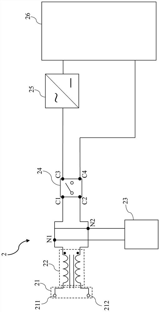
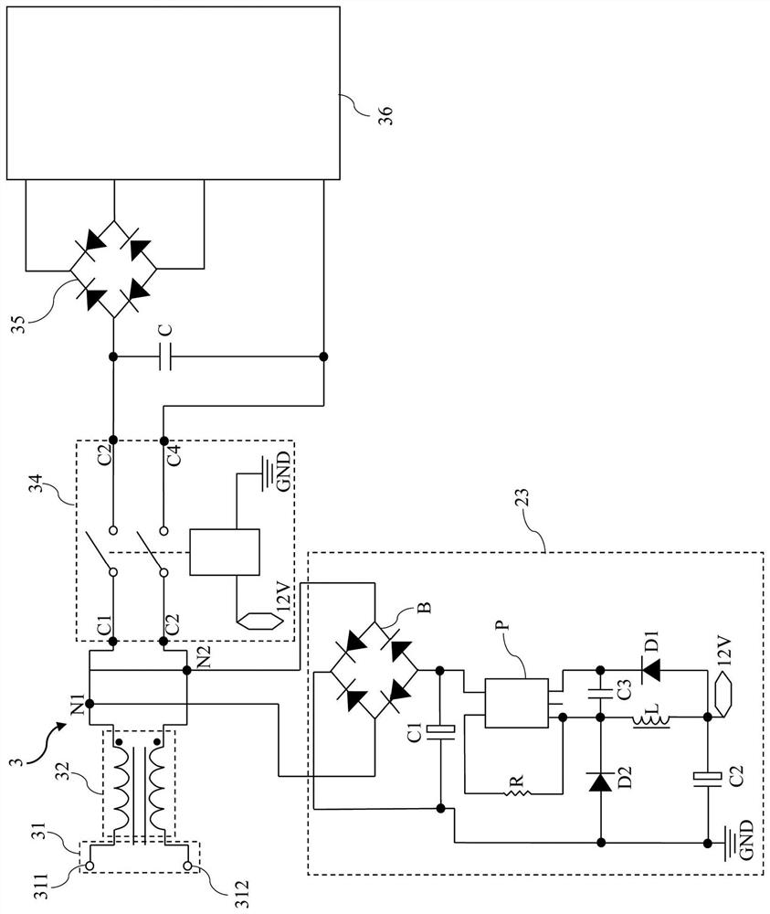
[0026] see figure 2 , which is a circuit diagram of the light-emitting diode lamp with the function of preventing afterglow according to the first embodiment of the present invention. As shown in the figure, the LED lamp 2 with the function of preventing afterglow includes a power supply input terminal 21 , a transformer circuit 22 , a control circuit 23 , a switch circuit 24 , a rectifier circuit 25 and a drive circuit 26 .

[0027] The power input terminal 21 includes a first power input terminal 211 and a second power input terminal 212 . In one embodiment, the first power input terminal 211 may be a live wire, and the second power input terminal 212 may be a neutral wire. In another embodiment, the first power input ter...


PUM


Abstract

A light-emitting diode lamp with a residual light prevention function comprises a power supply input end, a control circuit, a switching circuit, a rectifying circuit and a driving circuit. The power supply input end comprises a first power supply input end and a second power supply input end, the first power supply input end is connected with the first node, and the second power supply input end is connected with the second node. The control circuit is connected with the first node and the second node. The switching circuit comprises a first connecting end, a second connecting end, a third connecting end and a fourth connecting end. The first connecting end and the second connecting end are connected with the first node and the second node respectively. The driving circuit is used for connecting a plurality of light-emitting diodes, one end of the driving circuit is connected with the third connecting end through the rectifying circuit, and the other end of the driving circuit is connected with the fourth connecting end.

Description

technical field [0001] The present invention relates to a light-emitting diode lamp, in particular to a light-emitting diode lamp with the function of preventing afterglow. Background technique [0002] like figure 1 As shown, generally speaking, a light emitting diode (LED) lamp 1 is composed of a metal heat sink 11 (a metal part such as aluminum material), a lampshade 12 , a light emitting diode 13 (lamp bead) and a circuit board 14 (PCB board). In order to achieve a better heat dissipation effect, the circuit board 14 on which the light emitting diodes 13 are disposed needs to be as close to the metal heat sink 11 as possible. In addition, in order to meet the requirements of safety regulations, most of the metal heat sinks 11 are grounded. [0003] The power supply input end of the light-emitting diode lamp 1 has three wires, namely the live wire (L), the neutral wire (N) and the ground wire (P / PE). Wherein, the switch for controlling the light-emitting diode lamp 1 t...

Claims


Application Information

Patent Timeline
Patent Type & Authority Applications(China)
IPC IPC(8): H05B45/00H05B45/30
CPCH05B45/00H05B45/30H05B45/59H05B45/44H05B45/37
Inventor 卢福星林智荣
Owner XIAMEN PVTECH CO LTD
Why Eureka
Eureka Blog
Learn More