A multi-angle cake display stand that is easy to pick and place
A display rack and multi-angle technology, applied in the field of display racks, can solve problems such as inconvenient access, inconvenient cake observation, limited display angles of cake display racks, etc.
- Summary
- Abstract
- Description
- Claims
- Application Information
AI Technical Summary
Problems solved by technology
Method used
Image
Examples
Embodiment 1
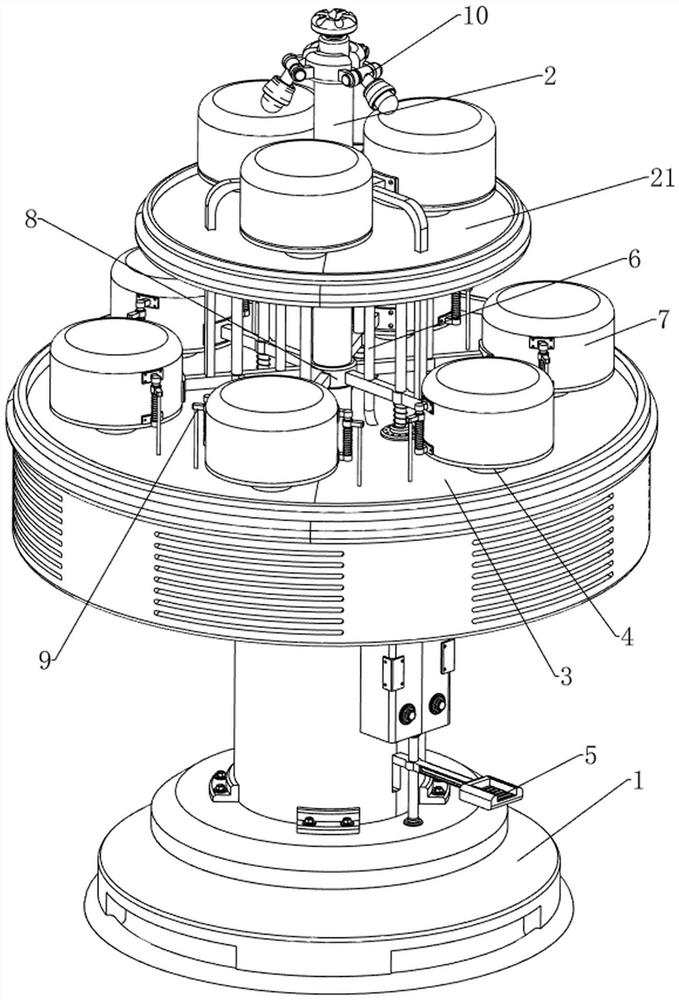
[0033] The present invention provides a multi-angle cake display rack that is easy to pick and place, see figure 1 and figure 2 , including a base 1, a rotating block 2, an upper disc 21, a lower disc 3 and a material holding plate 4, the middle part of the upper side of the base 1 is rotatably provided with a rotating block 2, and the upper part of the rotating block 2 is provided with an upper disc 21. The lower part of the rotating block 2 is provided with a lower disc 3, and the upper part of the upper disc 21 and the lower disc 3 are provided with a plurality of material holding plates 4.
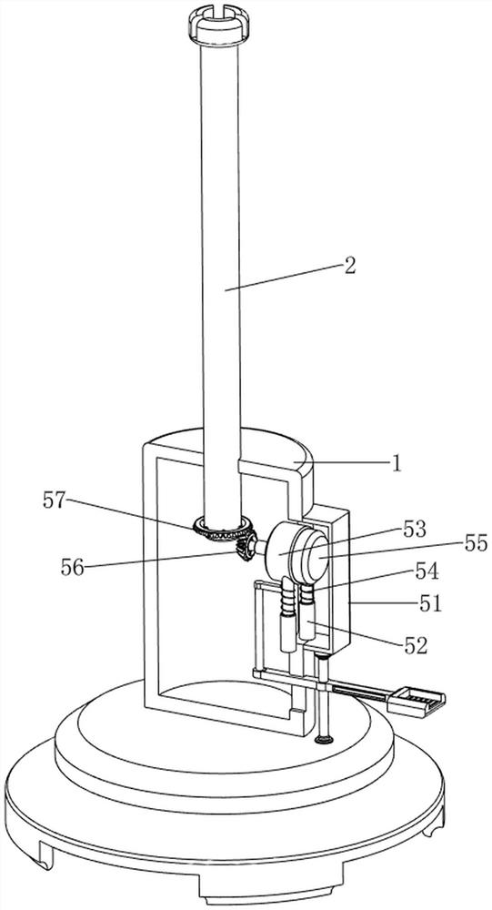
[0034] Drive mechanism 5 comprises mounting frame 51, hollow sleeve 52, telescopic block 53, first spring 54, reduction motor 55, first bevel gear 56 and second bevel gear 57, and the right side of base 1 top is provided with mounting frame 51, installs The frame 51 is provided with two hollow sleeves 52, and the upper parts of the two hollow sleeves 52 are slidably provided with a t...
Embodiment 2
[0037] On the basis of embodiment 1, refer to Figure 5 and Figure 6 , also includes a cover mechanism 7, the cover mechanism 7 includes a first slide bar 71, a second slide sleeve 72, a first glass cover 73, a third spring 74, a first bracket 75 and a second glass cover 76, the upper disk 21 and A plurality of first sliding rods 71 are evenly spaced between the middle parts of the lower disc 3, and the bottom of each first sliding rod 71 is slidably provided with a second sliding sleeve 72, and the bottom of each first sliding rod 71 is A third spring 74 is sheathed on the outside, and the two ends of the third spring 74 are respectively connected to the second sliding sleeve 72 and the first sliding rod 71 on the adjacent side, and the outside of each second sliding sleeve 72 is provided with The first glass cover 73, the middle part of the upper disk 21 is provided with three first brackets 75 slidingly, and the bottom of each first bracket 75 is connected with the seco...
Embodiment 3
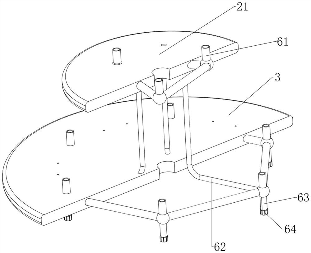
[0041] On the basis of embodiment 2, refer to image 3 , Figure 4 , Figure 7 and Figure 8 , also includes a limit mechanism 6, the limit mechanism 6 includes a suction cup 61, an air pipe 62, a punching cylinder 63, a blocking block 64, a first sliding sleeve 65 and a second spring 66, and the upper disc 21 and the lower disc 3 are provided with A plurality of suction cups 61, and each suction cup 61 is connected with a trachea 62, the bottom of each suction cup 61 on the lower side is provided with a punching tube 63, and the inner side of each punching tube 63 is provided with a first sliding sleeve 65, adjacent to each other A blocking block 64 is slidably provided between the first sliding sleeve 65 on one side and the outlet tube 63 , and a second spring 66 is provided between the blocking block 64 on the adjacent side and the first sliding sleeve 65 .
[0042] Also comprise pulling mechanism 9, and pulling mechanism 9 comprises the 3rd slide bar 91, the 3rd sliding...
PUM
 Abstract
Description
Claims
Application Information
 - R&D
- Intellectual Property
- Life Sciences
- Materials
- Tech Scout
- Unparalleled Data Quality
- Higher Quality Content
- 60% Fewer Hallucinations
Browse by: Latest US Patents, China's latest patents, Technical Efficacy Thesaurus, Application Domain, Technology Topic, Popular Technical Reports.
© 2025 PatSnap. All rights reserved.Legal|Privacy policy|Modern Slavery Act Transparency Statement|Sitemap|About US| Contact US: help@patsnap.com


