Pipe braiding machine for composite plastic pipe production and using method thereof
The technology of a plastic pipe and a pipe braiding machine is applied in the field of composite plastic pipe production equipment, which can solve the problem of time-consuming protective tape rolls, and achieve the effect of improving work efficiency and saving time.
- Summary
- Abstract
- Description
- Claims
- Application Information
AI Technical Summary
Problems solved by technology
Method used
Image

Examples
Embodiment Construction
[0033] In order to make the technical means, technical features, invention objectives and technical effects realized by the present invention easy to understand, the present invention will be further described below in conjunction with specific illustrations.
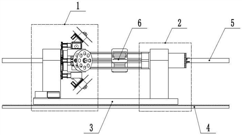
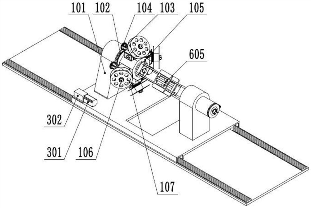
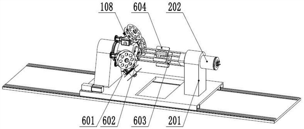
[0034] Such as figure 1 As shown in -6, a kind of braiding machine for composite plastic pipe production provided by the present invention includes a slide rail 4, a translation base 3 slidably connected on the slide rail 4, and the translation base 3 is provided with a winding mechanism 1 and a heating Mechanism 2, a guide mechanism 6 is provided between the winding mechanism 1 and the heating mechanism 2, the winding mechanism 1 is used to wrap the protective tape on the plastic pipe 5, and the heating mechanism 2 is used to connect the protective tape and the plastic pipe 5 is heated at the joint, so that the protective tape and the plastic pipe 5 are bonded together to form a composite plastic pipe 5, and the guide ...
PUM
 Abstract
Description
Claims
Application Information