Large antenna with rubber shock insulation structure

A rubber and antenna technology, applied to antennas, antenna components, antenna supports/installation devices, etc., can solve problems such as easy deformation, damage and collapse, and hidden dangers of earthquake damage, and achieve a simple and reliable structure and easy installation and the effect of maintenance

Pending Publication Date: 2021-08-31
NO 54 INST OF CHINA ELECTRONICS SCI & TECH GRP
View PDF0 Cites 0 Cited by
  • Summary
  • Abstract
  • Description
  • Claims
  • Application Information

AI Technical Summary

Problems solved by technology

Therefore, in addition to some large-scale antennas that have been built, some equipment that has not been built may also be built on the seismic zone, which poses a risk of earthquake damage
If an earthquake occurs, the large antenna with huge height, weight and volume will directly bear the impact and vibration brought by the seismic wave, and it is very easy to deform, damage and collapse, and the consequences will be disastrous

Method used


Image

  • Large antenna with rubber shock insulation structure
  • Large antenna with rubber shock insulation structure

Examples


Embodiment Construction

[0024] Below, the content of the present invention will be further clarified through specific embodiments. Of course, the following specific embodiments are described only to illustrate different aspects of the present invention, and should not be construed as limiting the scope of the present invention.

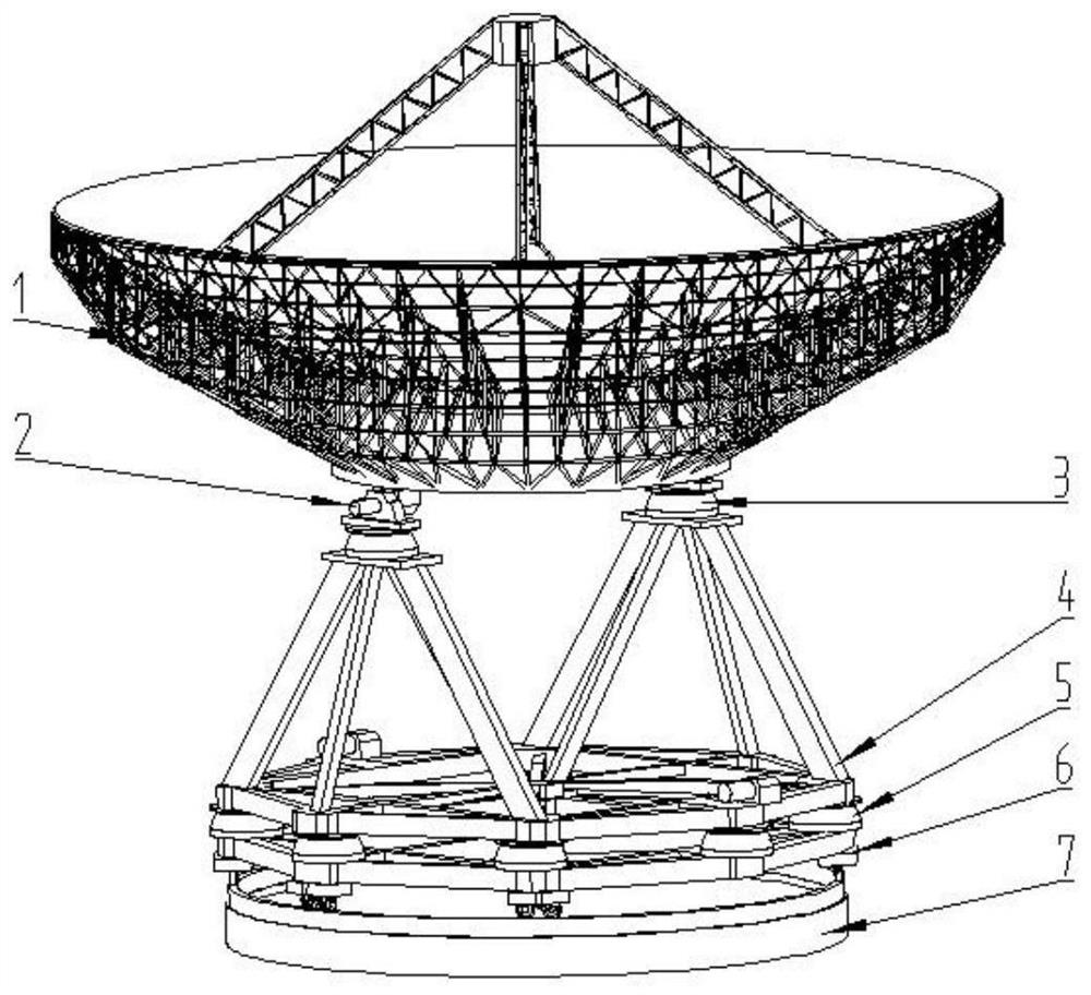
[0025] A large-scale antenna with a rubber shock-isolation structure includes a reflector, a mount carrying the reflector, an azimuth rotation structure, and a rubber shock-isolation structure; the rubber shock-isolation structure is located between the mount and the reflector.

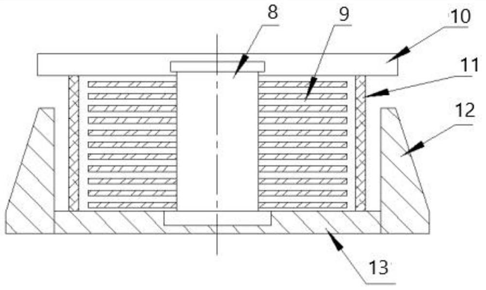
[0026] Further, the rubber shock-isolation structure includes an upper seat plate and a lower seat plate, the upper seat plate and the lower seat plate are parallel to each other, and a lead core column perpendicular to it is arranged between the two, and the outer wall of the lead core column is covered with There is a rubber steel plate spacer layer; the rubber steel plate spacer layer is a rubber...


PUM


Abstract

The invention discloses a large antenna with a rubber shock insulation structure, and belongs to the technical field of antennas. The antenna comprises a reflector, an antenna seat frame for bearing the reflector, an orientation rotation structure and a rubber shock insulation structure; and the rubber shock insulation structure is at least located at one of the following positions: between the seat frame and the reflector, and between the seat frame and the azimuth rotating structure. The antenna is stable in state and does not affect accurate operation of the antenna when an earthquake does not occur, can effectively play a role in shock isolation and shock absorption in the earthquake occurrence process, and has the advantages of light weight, low cost, easiness in installation and replacement and the like.

Description

technical field [0001] The invention relates to the technical field of antennas, in particular to a large-scale antenna with a rubber shock-isolation structure. Background technique [0002] With the rapid development of society's scientific and technological capabilities, radio astronomy has entered the era of high-sensitivity large samples, and large radio telescope antennas have played an important role in it. Human beings' desire for deeper and more urgent exploration of space has further driven the demand for the construction of large-scale radio telescope antennas, especially large-scale fully movable reflector telescope antennas with a diameter of about 50 meters or even more than 100 meters. [0003] Usually, the main structure of such a large antenna mainly includes two parts, that is, a mount part and a reflector part. Among them, the reflector part is used as the functional part of the antenna. The reflector carries a huge reflective surface to receive electroma...

Claims


Application Information

Patent Timeline
Patent Type & Authority Applications(China)
IPC IPC(8): H01Q1/00H01Q1/12H01Q19/12F16F15/08
CPCF16F15/08H01Q1/005H01Q1/12H01Q19/12
Inventor 曹江涛张晓冲金立斌王晓骁牛传峰张济良孙琪常硕董培松马剑南
Owner NO 54 INST OF CHINA ELECTRONICS SCI & TECH GRP
Why Eureka
Try Eureka