Eureka AIR delivers breakthrough ideas for toughest innovation challenges, trusted by R&D personnel around the world.

Water quality monitoring equipment

A technology for water quality monitoring and equipment, applied in testing water, measuring devices, material inspection products, etc., can solve problems such as increased power loss, loosening of bolts, and easy shaking of support rods, and achieves improved service life, good dryness, and reduced The effect of loss of electrical energy

Inactive Publication Date: 2021-09-03
莱西市济蓝环境生态科技院
View PDF1 Cites 0 Cited by
  • Summary
  • Abstract
  • Description
  • Claims
  • Application Information

AI Technical Summary

Problems solved by technology

[0005] In order to solve the above-mentioned technical problems, the present invention provides a water quality monitoring device to solve the problem that when the above-mentioned device brushes the monitoring probe, the brushing mechanism needs to be driven by a motor to complete the brushing operation, which not only increases the loss of electric energy, but also the motor in the water Even if there is a cover, there will still be hidden dangers of water ingress, and because the above-mentioned equipment is connected by bolts to the side of the sewage pool, the support rod is easily shaken under the impact of pool water and external wind, so that the base and the sewage pool The bolts connected between the sides are prone to loosening, and due to the lack of an effective drying structure inside the control box of the above-mentioned equipment, the inside of the control box next to the sewage pool is very easy to enter humid air, thereby reducing the service life of the electrical components inside the control box. question

Method used


Image

  • Water quality monitoring equipment
  • Water quality monitoring equipment
  • Water quality monitoring equipment

Examples


Embodiment

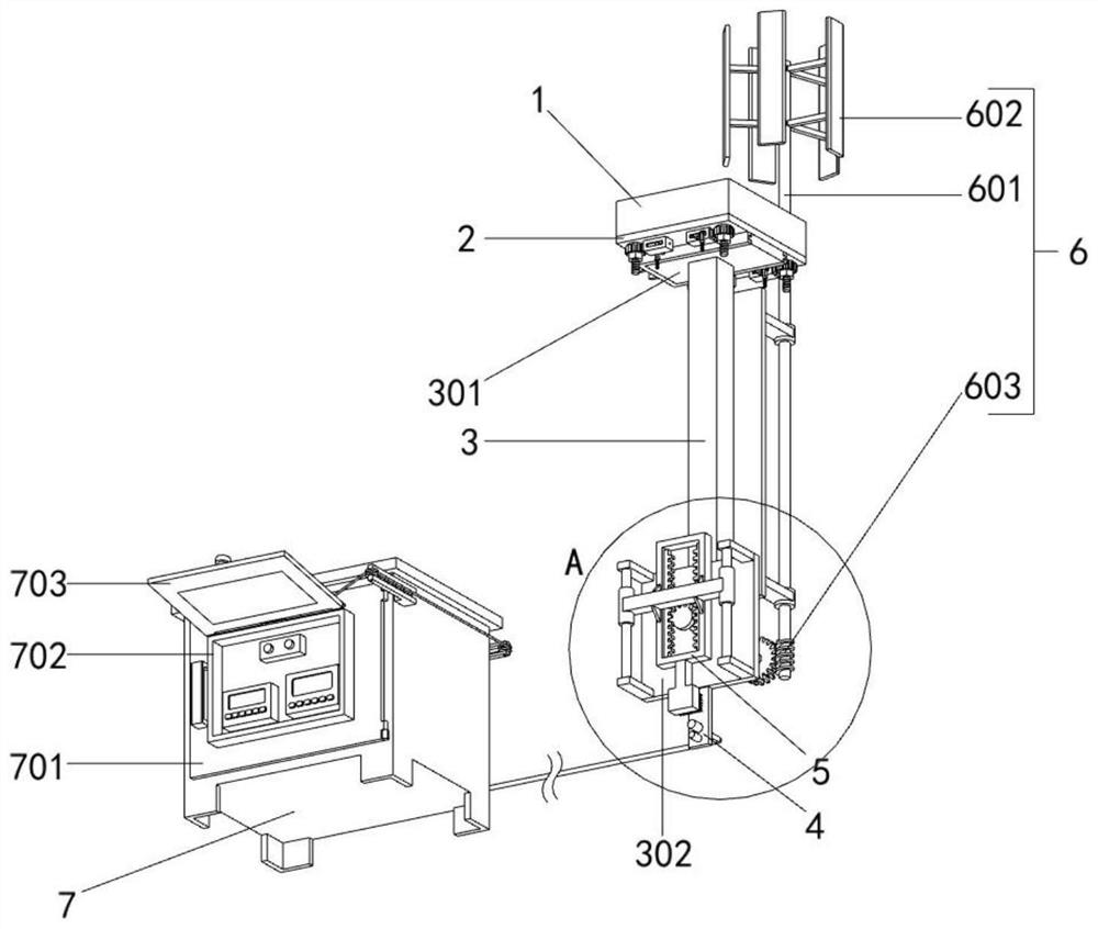
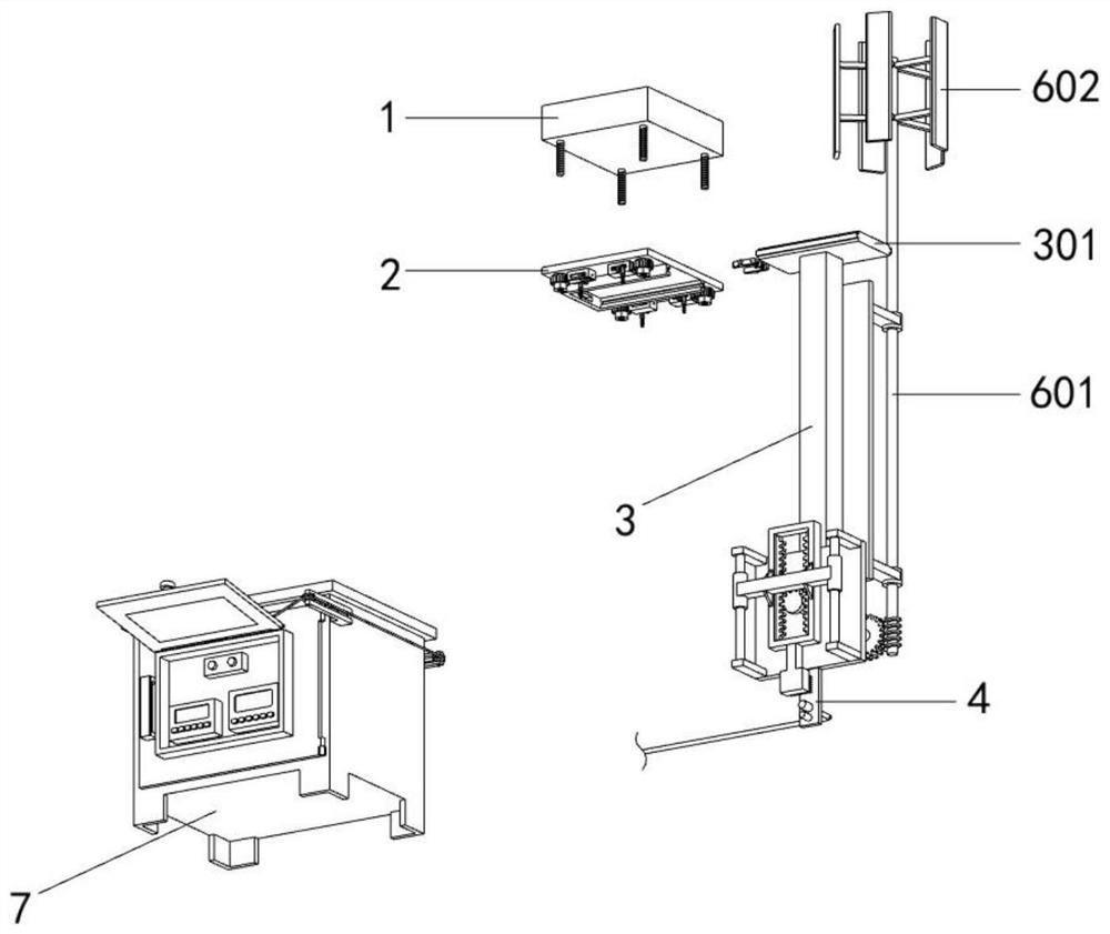
[0035] as attached figure 1 to attach Figure 8 Shown:

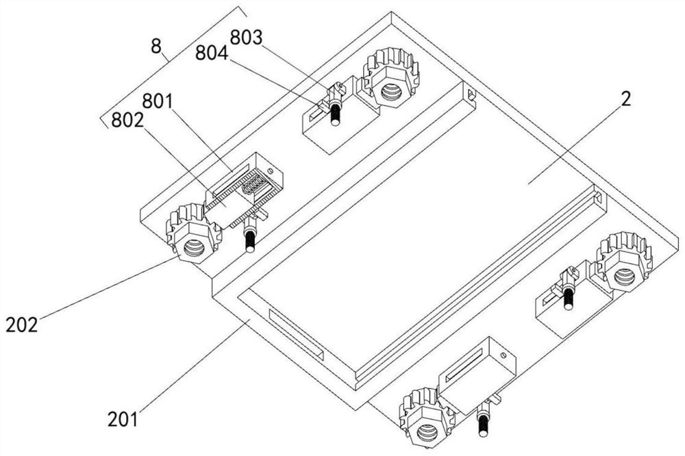
[0036] The present invention provides a water quality monitoring device, comprising: a concrete support 1; the bottom end surface of the concrete support 1 is connected with a mounting seat 2 through four studs; the mounting seat 2 includes a connecting block 201 and a fastening nut 202, and the mounting seat 2 The middle part of the bottom end surface is provided with a connecting block 201, and the connecting block 201 is a U-shaped structure. T-shaped slide grooves are provided on the front and rear sides of the inner side of the connecting block 201, and the inner side of the connecting block 201 is slidably connected to the support rod 3. The left end surface of the connecting block 201 There is a rectangular bayonet in the middle; the number of fastening nuts 202 is four, and the four fastening nuts 202 are respectively connected to the four studs at the bottom of the concrete support 1 through threads, and the ou...


PUM


Abstract

The invention provides water quality monitoring equipment, belongs to the technical field of water quality monitoring equipment, and aims to solve the problems that when the equipment is used for brushing a monitoring probe, the brushing operation can be completed only through a motor, so the electric energy loss is increased, and the hidden danger that water enters the motor in water exists. The equipment comprises a concrete support; the bottom end face of the concrete support is connected with a mounting base through four studs, a supporting rod is mounted at the bottom of the mounting base, and four limiting mechanisms are arranged at the bottom of the mounting base. A monitoring probe is arranged at the lower end of the supporting rod. Through cooperation of the wind power driving part and the brushing mechanism, the vertical wind power driving part drives the driving part to reciprocate up and down under the action of external wind power, so that the brush performs reciprocating sweeping up and down on the front side of the monitoring probe, the front side of the monitoring probe is effectively brushed, and the brushing mechanism does not need to be driven by a motor, so the loss of electric energy is reduced, and the hidden danger that water enters the motor is avoided.

Description

technical field [0001] The invention belongs to the technical field of water quality monitoring equipment, and more specifically relates to a water quality monitoring equipment. Background technique [0002] Water quality monitoring is the process of monitoring and measuring the types of pollutants in the water body, the concentration and change trend of various pollutants, and evaluating the water quality status. The scope of monitoring is very wide, including unpolluted and polluted natural water (river, river, lake, sea and groundwater) and various industrial drainage. When monitoring water quality, water quality monitoring equipment is usually used. [0003] For example, application number: CN202010233144.7 The present invention discloses a water quality monitoring device applied to sewage treatment, including: a control mechanism; a brushing mechanism, the brushing mechanism is electrically connected to the control mechanism; a support rod, the support rod is detachabl...

Claims


Application Information

Patent Timeline
Patent Type & Authority Applications(China)
IPC IPC(8): G01N33/18B01D53/26B08B1/00
CPCG01N33/1886B01D53/26B08B1/00
Inventor 刘恒芳
Owner 莱西市济蓝环境生态科技院
Why Eureka
Eureka Blog
Learn More