Eureka AIR delivers breakthrough ideas for toughest innovation challenges, trusted by R&D personnel around the world.

Automatic clamping device for vacuum glue injection pipeline

A technology for automatic clamping and injection of hoses. It is used in devices and coatings that apply liquid to the surface. It can solve the problems of long operation time, inability to realize automatic control of production lines, and low production efficiency.

Pending Publication Date: 2021-09-07
WUHAN HANGJIU ELECTRIC
View PDF8 Cites 1 Cited by
  • Summary
  • Abstract
  • Description
  • Claims
  • Application Information

AI Technical Summary

Problems solved by technology

However, the current vacuum injection production line uses a manual pipeline clamping device to stop and stop the rubber hose. Since multiple rubber hoses are involved in stopping and stopping, multiple people are required to operate, so it is impossible to realize the overall automatic control of the production line, and there are long operating hours and low production efficiency. , the problem of inaccurate glue filling control, so there is an urgent need for an automatic clamping device for vacuum glue injection pipelines

Method used


Image

  • Automatic clamping device for vacuum glue injection pipeline
  • Automatic clamping device for vacuum glue injection pipeline
  • Automatic clamping device for vacuum glue injection pipeline

Examples


Embodiment Construction

[0025] In order to make the purpose, technical solution and advantages of the present invention clearer, the embodiments of the present invention will be further described below in conjunction with the accompanying drawings.

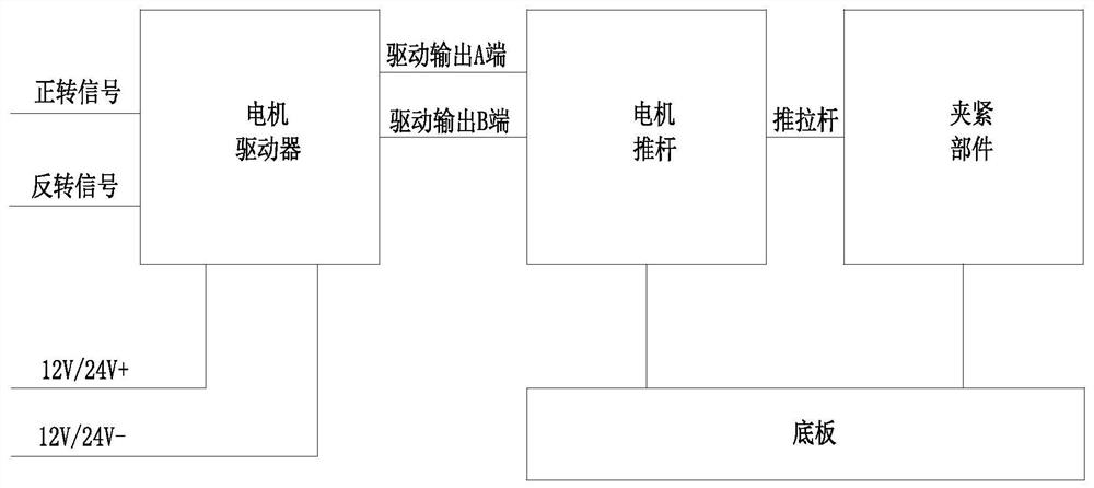
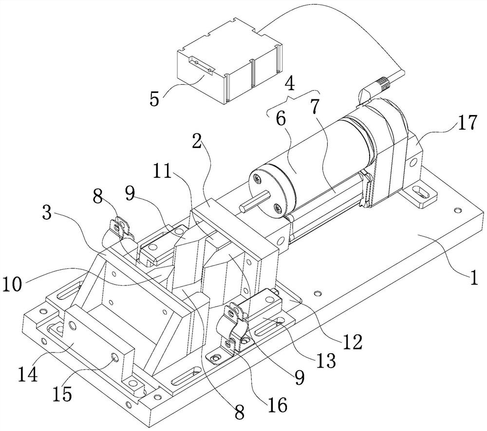
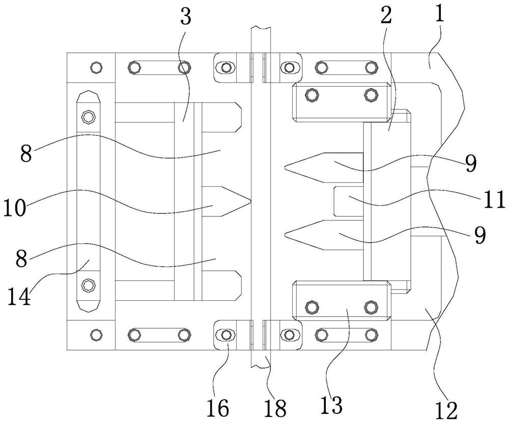
[0026] Please refer to figure 1 and 2 , an embodiment of the present invention provides an automatic clamping device for a vacuum glue injection pipeline, including a clamping component and a power component, wherein the clamping component is an execution component for directly clamping or releasing the glue pipe 18 for conveying glue; The power component is used as a driving component of the clamping component to provide driving power for the clamping component.

[0027] The clamping part includes a bottom plate 1 , a movable block 2 linearly slidably arranged on the bottom plate 1 , and a fixed block 3 opposite to the movable block 2 . specific:

[0028] The bottom plate 1 is a horizontal plate fixedly arranged for carrying the movable block 2 and t...


PUM


Abstract

The invention provides an automatic clamping device for a vacuum glue injection pipeline, comprising a clamping component and a power component. The clamping component comprises a bottom plate, a movable block linearly arranged on the bottom plate in a sliding mode, and a fixed block arranged opposite to the movable block; one of the two opposite side surfaces of the movable block and the fixed block is provided with at least one groove, the other one of the two opposite side surfaces of the movable block and the fixed block is provided with at least one protruding block, and the grooves match the protruding blocks; the power component is connected with the movable block and used for driving the movable block to linearly move back and forth, so that when the movable block gets close to the fixed block, the protruding blocks enter the grooves so as to extrude and clamp a rubber pipe, and when the movable block gets away from the fixed block, the protruding blocks are separated from the grooves so as to release the rubber pipe. The device has the beneficial effects that the grooves and the protruding blocks match to clamp, stop or release and open the glue pipe, so that automatic control and accurate control on the glue injection amount in the vacuum glue injection process are realized, and the production efficiency of vacuum glue injection is improved.

Description

technical field [0001] The invention relates to the technical field of vacuum glue injection equipment, in particular to an automatic clamping device for vacuum glue injection pipelines. Background technique [0002] Vacuum glue injection is glue filling in a vacuum environment. It is widely used in industries such as automobile manufacturing and capacitor coil glue filling with complex product structures. Vacuum glue injection has the advantages of excellent glue quality, cycle work ability, and high production efficiency. At present, in the vacuum glue injection production line, the glue is generally vacuumized in the vacuum box to remove air bubbles, and then the glue is drawn out by the rubber hose under the vacuum and flows into the mold through the rubber hose for glue filling. During the glue filling process, it is necessary to control the entrance of the glue hose. stop to accurately control the amount of glue poured. However, the current vacuum injection production...

Claims


Application Information

Patent Timeline
Patent Type & Authority Applications(China)
IPC IPC(8): B05C11/10
CPCB05C11/1013
Inventor 苏锦宏王党生李浩程林林张家贵盖忠伟魏彦王俊炎
Owner WUHAN HANGJIU ELECTRIC
Why Eureka
Eureka Blog
Learn More