
Energy-saving type new energy vehicle windscreen wiper driving structure

A new energy vehicle, energy-saving technology, applied in vehicle maintenance, vehicle cleaning, transportation and packaging, etc., can solve problems such as shortening the distance, consuming vehicle power, distracting the driver's attention, etc., to achieve the effect of extending the distance and saving energy

Inactive Publication Date: 2021-09-07
HUZHOU YUEBIN INTELLIGENT TECH CO LTD
View PDF0 Cites 0 Cited by
  • Summary
  • Abstract
  • Description
  • Claims
  • Application Information

AI Technical Summary

Problems solved by technology

[0003] During the use of the wiper, the driver can manually start it, and according to the actual demand, that is, the amount of rainfall, the gear position of the wiper is controlled, and the interval time between the wiper and the wiper is adjusted. When the existing wiper is in use, the generally used It is the electric energy inside the car. For new energy vehicles, using the wiper for a long time in rainy days will consume a lot of electric energy of the car, thereby shortening the distance that the car can travel within the limited electric energy, causing inconvenience to people's travel, and the wiper passes through the driver. Manual control can be adjusted. On the one hand, it is easy to distract the driver's attention when driving. On the other hand, if the driver forgets to turn off the wiper when the rain decreases or stops, it is easy to cause waste of electric energy. Therefore, it is necessary to design an energy-saving New energy vehicle wiper drive structure to solve the above problems

Method used


Image

  • Energy-saving type new energy vehicle windscreen wiper driving structure
  • Energy-saving type new energy vehicle windscreen wiper driving structure
  • Energy-saving type new energy vehicle windscreen wiper driving structure

Examples


Embodiment Construction

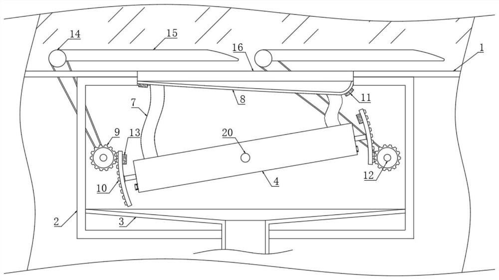
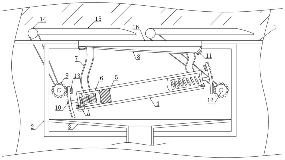
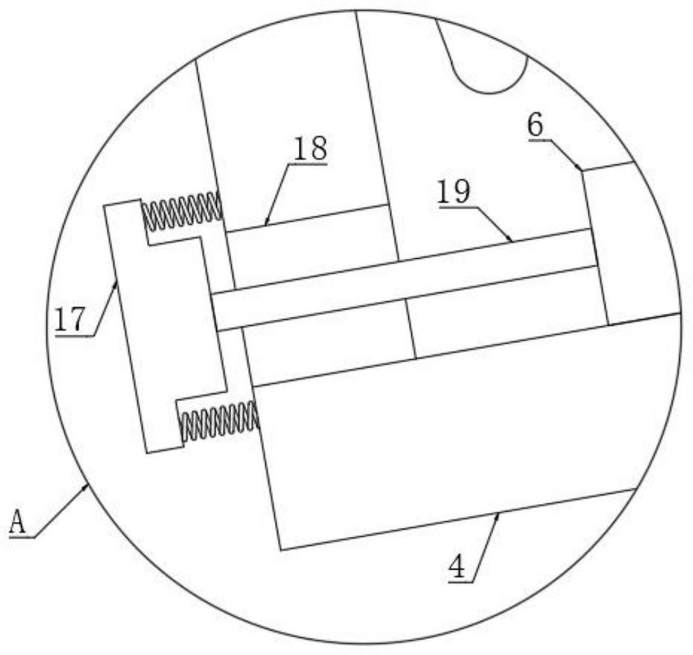
[0023] The following will clearly and completely describe the technical solutions in the embodiments of the present invention with reference to the accompanying drawings in the embodiments of the present invention. Obviously, the described embodiments are only some, not all, embodiments of the present invention.

[0024] refer to Figure 1-3 , an energy-saving new energy vehicle wiper driving structure, including a front body 1, two rotating shafts 14 are arranged on the upper end of the front body 1, and the side walls of the two rotating shafts 14 are fixedly connected with a wiper 15. In the initial state, the two wipers 15 All are in a horizontal state, and the inner wall of the front body 1 is fixedly connected with the installation box 2 .

[0025] The interior of the installation box 2 is provided with a drive mechanism for driving the rotation of the two wipers 15. The drive mechanism includes a rotation rod 20 that is rotatably connected to the inner wall of the insta...


PUM


Abstract

The invention discloses an energy-saving new energy vehicle windscreen wiper driving structure which comprises a front automobile body, two rotating shafts are arranged at the upper end of the front automobile body, windscreen wipers are fixedly connected to the side walls of the two rotating shafts, and a mounting box is fixedly connected to the inner wall of the front automobile body; a driving mechanism used for driving the two windscreen wipers to rotate is arranged in the mounting box, the driving mechanism comprises a rotating rod rotationally connected to the inner wall of the mounting box, one end of the rotating rod is fixedly connected with a rotating box, and the inner wall of the rotating box is elastically connected with two moving plates through two pressure springs; a moving block is slidably connected to the inner wall of the rotating box, drainage ports are formed in the two side walls of the rotating box in a penetrating mode, and sealing plugs are elastically connected to the two side walls of the rotating box through a plurality of springs. The windscreen wiper can be automatically started in rainy days, manual control of a driver is not needed, electric energy in the automobile does not need to be used, energy is greatly saved, and the driving distance of the new energy vehicle is prolonged.

Description

technical field [0001] The invention relates to the technical field of new energy automobile accessories, in particular to an energy-saving new energy automobile wiper driving structure. Background technique [0002] Wipers, also known as wipers, water dials, wipers or windshield wipers, are devices used to scrape off raindrops and dust attached to the windshield of vehicles to improve the visibility of drivers and increase driving safety. [0003] During the use of the wiper, the driver can manually start it, and according to the actual demand, that is, the amount of rainfall, the gear position of the wiper is controlled, and the interval time between the wiper and the wiper is adjusted. When the existing wiper is in use, the generally used It is the electric energy inside the car. For new energy vehicles, using the wiper for a long time in rainy days will consume a lot of electric energy of the car, thereby shortening the distance that the car can travel within the limited...

Claims


Application Information

Patent Timeline
Patent Type & Authority Applications(China)
IPC IPC(8): B60S1/06B60S1/12
CPCB60S1/06B60S1/12
Inventor 徐辉
Owner HUZHOU YUEBIN INTELLIGENT TECH CO LTD
Learn More