Battery cooling structure for electric vehicle

a technology for electric vehicles and cooling structures, applied in battery/fuel cell control arrangements, cell components, batteries, etc., can solve the problems of high cost prohibitive in relation to its commercial value, and unfavorable electric vehicle transportation. achieve the effect of increasing the traveling distance of electric vehicles, improving power performance, and effectively cooling a plurality of battery packs

Inactive Publication Date: 2012-12-13
HYUNDAI MOTOR CO LTD +1
View PDF9 Cites 40 Cited by
  • Summary
  • Abstract
  • Description
  • Claims
  • Application Information

AI Technical Summary

Benefits of technology

[0009]The present invention has been made in an effort to provide a battery cooling structure for an electric vehicle that can cool a battery generating heat by forming a cooling channel that induces the flow of air to the outside of a plurality of batteries mounted in an electric vehicle and blowing air into a cooling channel, in order to effectively cool the batteries.
[0016]According to the exemplary embodiments of the present invention, it is possible to an increase the traveling distance of the electric vehicle and improve the power performance by mounting a battery pack in the console in the center in the vehicle, under the second-row seat (i.e., the back seat), and the trunk. Further, it is possible to effectively cool a plurality of battery packs mounted in an electric vehicle, by cooling the battery pack via uniformly supplying air in the vehicle, with the battery packs positioned in a cooling channel that can control the flow of air in the vehicle.

Problems solved by technology

However, they are necessarily limited as such.
However, the batteries generate heat when they are being operated, and thus they require system or device to control this generated heat to prevent overheating.
The water-cooling based system has excellent cooling performance, but is relatively complicated and is highly cost prohibitive in relation to its commercial value, such that the air-cooling type is more often used than the water-cooling type.
However, even these free-air cooling based systems of an electric vehicle using the air-cooling type, a technology of systematically cooling the battery is not applied and the battery is cooled by blowing only air.

Method used


Image

  • Battery cooling structure for electric vehicle
  • Battery cooling structure for electric vehicle
  • Battery cooling structure for electric vehicle

Examples


Embodiment Construction

[0031]Reference will now be made in detail to various embodiments of the present invention(s), examples of which are illustrated in the accompanying drawings and described below. While the invention(s) will be described in conjunction with exemplary embodiments, it will be understood that present description is not intended to limit the invention(s) to those exemplary embodiments. On the contrary, the invention(s) is / are intended to cover not only the exemplary embodiments, but also various alternatives, modifications, equivalents and other embodiments, which may be included within the spirit and scope of the invention as defined by the appended claims.

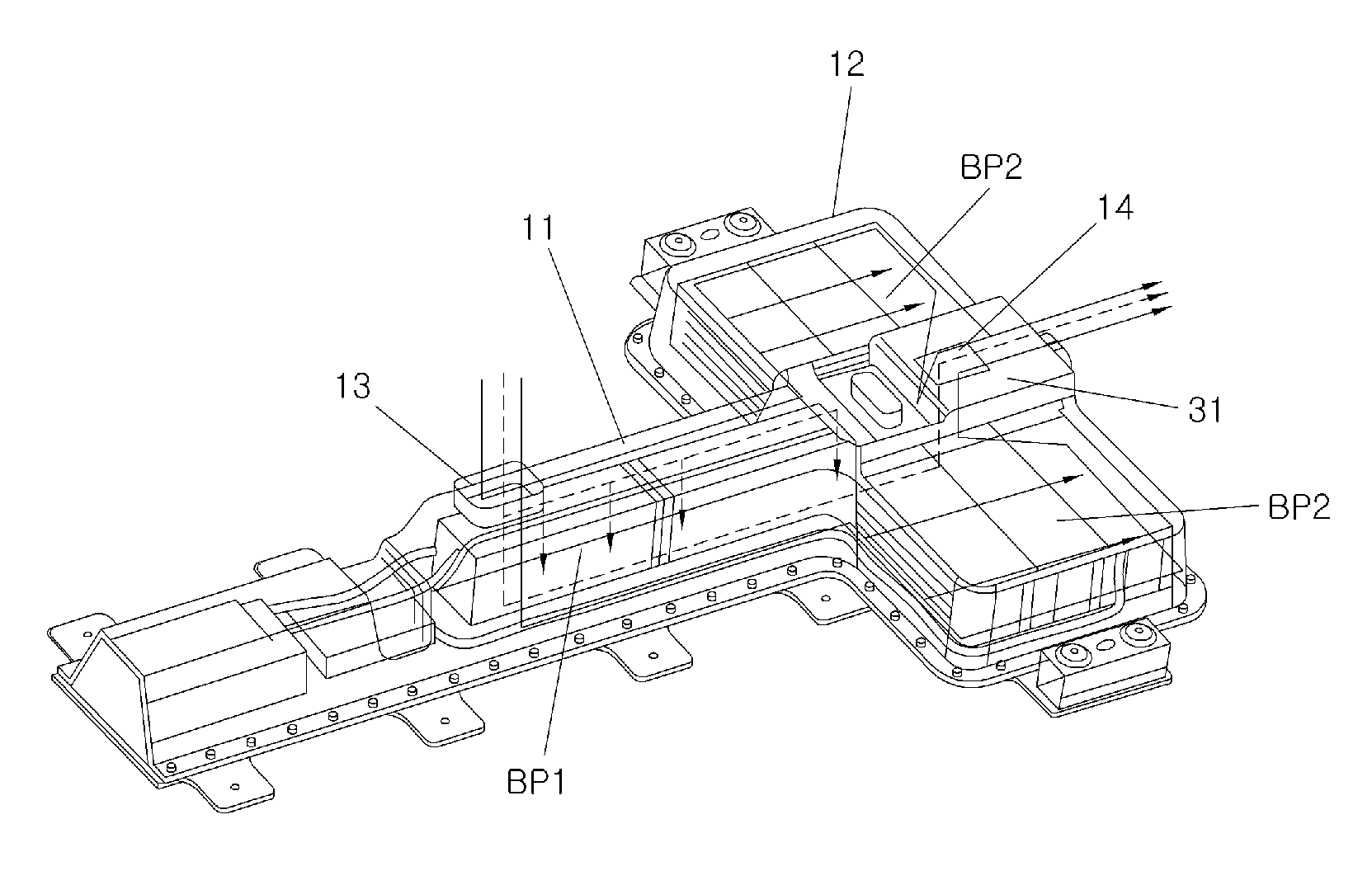
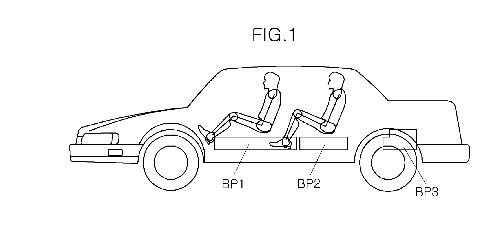
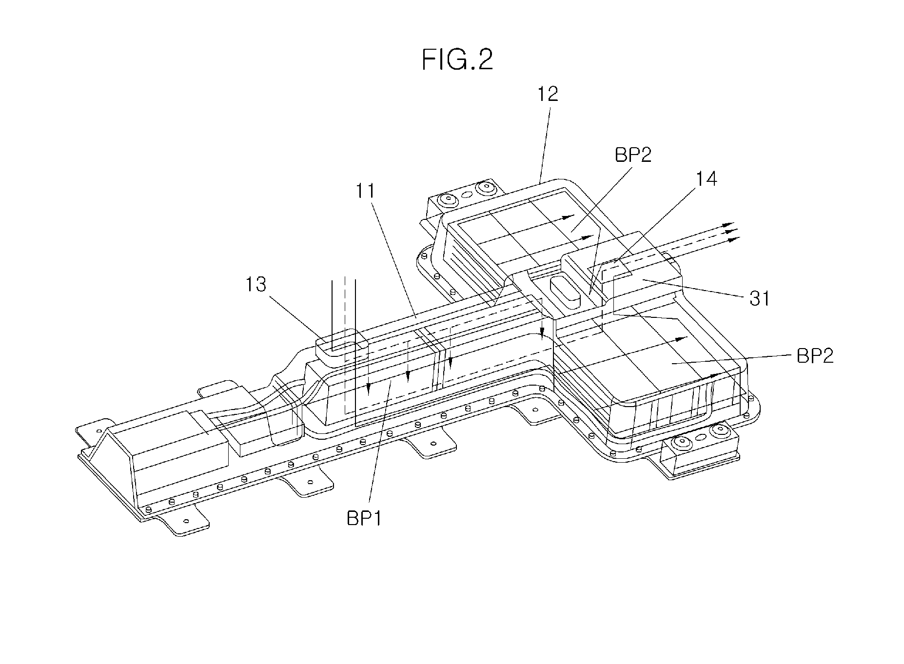
[0032]A battery cooling structure for an electric vehicle according to an exemplary embodiment of the present invention is described with reference to the accompanying drawings. A battery cooling structure for an electric vehicle according to an exemplary embodiment of the present invention includes a plurality of battery packs BP1, B...


PUM

PropertyMeasurementUnit
widthaaaaaaaaaa
traveling distanceaaaaaaaaaa
power performanceaaaaaaaaaa

Abstract

Disclosed is a battery cooling structure for an electric vehicle which can cool a plurality of batteries mounted in the electric vehicle by forming a cooling channel around the batteries and blowing air therethrough. In the battery cooling structure for an electric vehicle disclosed herein, a first battery pack is disposed in the longitudinal direction of the vehicle, between a first-row of seats in the vehicle, a first battery housing is provided which is configured to allow through the first battery housing from the interior of the vehicle and is formed in the longitudinal direction to accommodate the first battery pack, and a first fan is disposed in the first housing to force the air in the vehicle into the first battery housing to be discharged to a trunk after cooling the first battery pack.

Description

CROSS-REFERENCE TO RELATED APPLICATIONS[0001]The present application claims priority to Korean Patent Application Number 10-2011-0056135 filed Jun. 10, 2011, the entire contents of which application is incorporated herein for all purposes by this reference.BACKGROUND OF THE INVENTION[0002]1. Field of the Invention[0003]The present invention relates to a battery cooling structure for an electric vehicle, and more particularly, to a battery cooling structure for an electric vehicle that can cool a plurality of batteries by blowing air, and by forming a cooling channel around the batteries disposed in the electric vehicle.[0004]2. Description of Related Art[0005]Recently, there has been an active movement towards developing technology relating to hybrid vehicles and electric vehicle due to the rising oil prices, exhaustion of fossil energy and regulation related to clean air and pollution. The hybrid vehicle, however, has drawn particular attention because it uses two or more distinct ...

Claims


Application Information

Patent Timeline
Patent Type & Authority Applications(United States)
IPC IPC(8): B60K11/06H01M10/50B60K1/04H01M10/60H01M10/613H01M10/625H01M10/647H01M10/6563H01M10/6566H01M10/663H01M50/204
CPCH01M2/1077H01M10/5004H01M10/5016H01M10/5057B60K2001/005H01M10/5067H01M2220/20B60K1/04B60K11/06H01M10/5059H01M10/625H01M10/6563H01M10/6556H01M10/6557H01M10/613Y02E60/10Y02T10/70H01M50/204B60L58/26B60Y2400/89B60Y2200/91
Inventor KIM, DALKIM, MINWOOKYOON, SHINHYUKBANG, JUNHO
Owner HYUNDAI MOTOR CO LTD
Why Eureka
Try Eureka