Wind tunnel simulation device

A simulation device and wind tunnel technology, applied to measuring devices, instruments, aerodynamic tests, etc., can solve problems such as difficulty in processing, many changes in wind force, and inability to simulate one by one, and achieve a variety of effects

Active Publication Date: 2021-09-07
CHANGSHA UNIVERSITY OF SCIENCE AND TECHNOLOGY
View PDF9 Cites 0 Cited by
  • Summary
  • Abstract
  • Description
  • Claims
  • Application Information

AI Technical Summary

Problems solved by technology

[0004] 1. The experimental system of the prior art controls the wind force through a valve. However, the wind force in the actual situation is often changing rapidly, and there are too many wind force changes, which cannot be simulated one by one.
[0005] 2. In the valves of the prior art, there are composite spools, but the composite spool is often the inner spool as an auxiliary valve, the outer spool as the main valve, and the inner spool is often processed due to its small volume. Difficulty, and the functions and execution area that the small-volume spool can perform are small, which affects the effect
[0006] 3. The valves in the prior art can adjust the flow through the degree of opening and closing, but the control of the degree of opening and closing requires manual or machine control, which greatly increases the cost
[0007] 4. After the spool of the prior art is used for a long time, there will be fouling or maintenance is required. At this time, the spool needs to be disassembled, and the procedure is relatively cumbersome
[0008] 5. The spool through hole of the prior art is often square or circular, ignoring the characteristics of the oval through hole and the benefits brought by the cooperation of different shapes of through holes
[0009] 6. In the multi-channel rotary valve of the prior art, due to too many channels, the gap between the channels is greatly reduced for each additional channel, and there are less places for sealing, which brings difficulties to the processing and installation of the sealing structure
[0010] 7. The valves in the prior art work through a single drive, and there are few double drives, because the support and vibration of the drive parts are a big problem when the double drive is used
[0011] 8. The living and industrial valves in the existing technology are often set separately, but the experimental valve is just the opposite. Because the experimental valve simulates the actual situation but the ratio is greatly reduced, there is an integration requirement for the experimental valve, and ordinary valves obviously cannot meet the integration requirements.

Method used


Image

  • Wind tunnel simulation device
  • Wind tunnel simulation device
  • Wind tunnel simulation device

Examples


Embodiment Construction

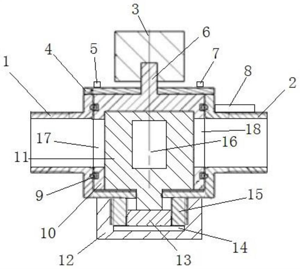
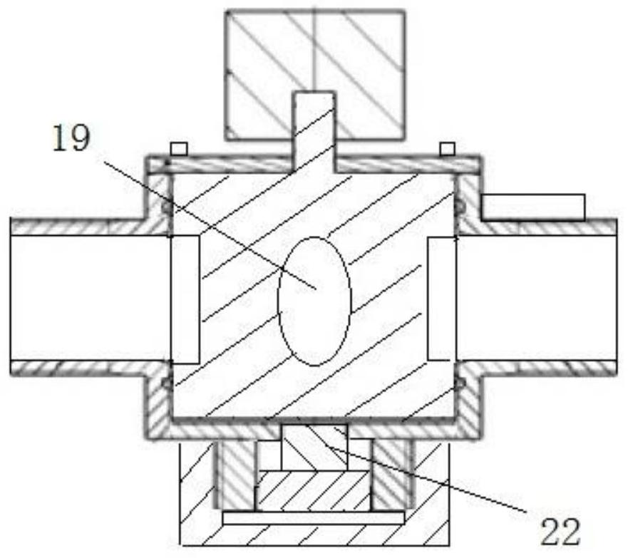
[0047] As shown in the figure: a wind tunnel simulation device, including a fan, an air inlet, an air outlet, a control valve, an air filter, and a main beam section model; wherein the main beam section model includes an edge, a main beam section, Suction port, suction pipeline, blowing port, external port 1, external port 2, blowing pipeline, the fan sucks air through the suction port, connects the air filter through the blowing port, and the air filter The output end is connected to the control valve, and the output end of the control valve outputs gas to blow to the edge of the main beam section model. The main beam section is provided with an external port 1 and an external port 2, and the external port 1 is connected to an external blower. Inhalation equipment, the external port two is connected to the external inhalation equipment, the edge is provided with an inhalation port and an air blowing port, the inhalation port is connected to the external inhalation equipment th...


PUM


Abstract

A wind tunnel simulation device comprises a fan, an air suction port, an air blowing port, a control valve, an air filter, a main beam segment model, an air suction port, an air suction pipeline, an air blowing port, an external port, a main beam section and an air blowing pipeline. The main beam section model comprises an edge and a main beam section, the fan sucks air through the air suction port and is connected with the air filter through the air blowing port, the output end of the air filter is connected with the control valve, the output end of the control valve outputs air and blows the air to the edge of the main beam section model, and the main beam section is provided with an external port. The external port is connected with external blowing equipment and external suction equipment, the edge of the external port is provided with a suction port and a blowing port, the suction port is connected with the external suction equipment through a suction pipeline and the external port, and the blowing port is connected with the external blowing equipment through a blowing pipeline and the external port; and air blowing and air suction through the air blowing port and the air suction port influence the air flow blowing to the edge.

Description

technical field [0001] The invention relates to the field of bridge vortex vibration experiments, in particular to a wind tunnel simulation device. Background technique [0002] With the increasing span of bridges, wind-induced vibration has gradually become the main factor restricting the further development of long-span bridges. Vortex vibration is a self-limiting wind-induced vibration phenomenon with dual characteristics of forced and self-excited, which is caused by the regular vortex shedding generated when the airflow passes through the surface of the structure. The phenomenon of vortex vibration of bridge girders is common in practical engineering, such as the Rio-Niteroi Bridge in Brazil, the Trans-Tokyo Bay Bridge in Japan, and the Great Belt Bridge in Denmark. East Belt Bridge), Volga Bridge in Russia, Verrazzano-Narrows Bridge in the United States, Xihoumen Bridge, Humen Bridge and Yingwuzhou Bridge in China all appeared in the course of operation. Different de...

Claims


Application Information

Patent Timeline
Patent Type & Authority Applications(China)
IPC IPC(8): G01M9/04G01M9/06
CPCG01M9/04G01M9/062
Inventor 胡朋王赛龙洪泽宇韩艳董国朝罗颖刘汉云李凯宋俊
Owner CHANGSHA UNIVERSITY OF SCIENCE AND TECHNOLOGY
Why Eureka
Try Eureka