
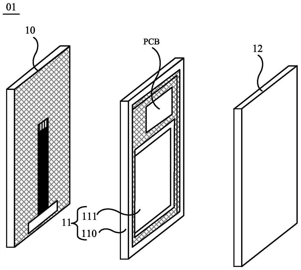
a mobile terminal

A mobile terminal and vibrator technology, which is applied to the structure of telephones, sensors, branch office equipment, etc., can solve problems such as increased impedance, insufficient high-frequency volume of mobile phones, and insufficient driving force of vibrators.

Active Publication Date: 2022-07-12
HUAWEI TECH CO LTD
View PDF9 Cites 0 Cited by
  • Summary
  • Abstract
  • Description
  • Claims
  • Application Information

AI Technical Summary

Problems solved by technology

However, the number of turns of a coil is proportional to its impedance, and when the sounding frequency is high, the impedance of the coil increases further as the sounding frequency increases
In this way, the sound of the screen is in the high-frequency band, and the current on the coil will decrease due to the increase of impedance, so that the driving force provided by the vibrator to the screen is insufficient, resulting in insufficient high-frequency volume from the mobile phone.

Method used


Image

  • a mobile terminal
  • a mobile terminal
  • a mobile terminal

Examples


example 1

[0061] In this example, when the size of the gap H between the carrier board 111 of the middle frame 11 and the back surface B of the display module 10 is limited, such as Figure 3a As shown, at least a portion of the vibrator 20 may be disposed within the accommodating cavity 103 .

[0062] The vibrator 20 described above may include, for example, Figure 3a A first magnet 201 , a second magnet 202 , a coil 200 and at least one third magnet 203 are shown. The first magnet 201 , the coil 200 and the third magnet 203 are all connected to the back surface B of the display module 10 . like Figure 3b As shown, the first magnet 201 may be located in a closed area where the wires of the coil 200 are wound. Furthermore, if Figure 3a As shown, the second magnet 202 is connected to the carrier plate 111 of the middle frame 11 . In addition, the second magnet 202 is disposed opposite to the position of the first magnet 201 .

[0063] In addition, in order to connect the first m...

example 2

[0104] This example is the same as Example 1, as Figure 3a As shown, at least a portion of the vibrator 20 may be disposed within the accommodating cavity 103 . The vibrator 20 includes a first magnet 201 , a second magnet 202 , a coil 200 and at least one third magnet 203 . The first magnet 201 , the coil 200 and the third magnet 203 may be disposed in the first magnetic isolation cover 41 . The third magnet 203 is disposed in the second magnetic isolation cover 42 . In addition, the vibrator 20 may further include a fourth magnet 204 disposed in the second magnetic isolation cover 42 .

[0105] The difference from Example 1 is that if Figure 12a As shown, the magnetization direction of the third magnet 203 is parallel to the display surface A of the display module 10 .

[0106] For the convenience of description below, in some embodiments of the present application, Figure 12a The shown structure is taken as an example, and the first pole of the magnet is N pole, and...


PUM


Abstract

Embodiments of the present application provide a mobile terminal, which relates to the technical field of screen sound production, and is used to improve the problem of insufficient volume in high frequency bands when the mobile terminal realizes screen sound production. At least a part of the vibrator in the mobile terminal is arranged in the accommodating cavity. The vibrator includes a first magnet, a second magnet, a coil, and at least one third magnet. The first magnet, the coil and the third magnet are all connected with the back of the display module. The first magnet is located in a closed area formed by the wires of the coil. The third magnet is located on the side of the coil away from the first magnet. The second magnet is connected with the middle frame, and the positions of the second magnet and the first magnet are arranged opposite to each other. The first pole of the first magnet, the first pole of the second magnet and the second pole of the third magnet are close to each other so that at least a portion of the magnetic field lines pass through the coil from the surface of the coil near the first magnet and the surface near the third magnet.

Description

technical field [0001] The present application relates to the technical field of screen sound generation, and in particular, to a mobile terminal. Background technique [0002] Users have higher and higher requirements on the screen ratio of mobile terminals, such as mobile phones. In order to increase the screen-to-body ratio of the mobile phone, a vibrator can be set on the back of the display screen of the mobile phone. The driving force provided by the vibrator to the display screen can drive the display screen to vibrate. In this case, the display screen can be used as a diaphragm to push the air to generate sound during the vibration process, so as to realize the sound of the screen. In this way, there is no need to punch holes on the front of the mobile phone and install an earpiece, so that the purpose of increasing the screen ratio of the mobile phone can be achieved. [0003] The vibrator is provided with a coil for generating the above-mentioned driving force. ...

Claims


Application Information

Patent Timeline
Patent Type & Authority Patents(China)
IPC IPC(8): H04M1/02
CPCH04M1/026H04M1/0266H04R9/04H04R9/02H04R2499/15H04R2499/11H04R9/025H04R7/04G06F1/1656H04M2201/08
Inventor 张成陈文浩
Owner HUAWEI TECH CO LTD
Learn More