Vibration motors

Inactive Publication Date: 2001-11-01
SAGEM DEFENSE SECURITE SA
View PDF0 Cites 8 Cited by
  • Summary
  • Abstract
  • Description
  • Claims
  • Application Information

AI Technical Summary

Benefits of technology

0014] In above-mentioned patent application FR 2 742 011, it is shown that such a structure has the advantage of limiting the peaks of the applied normal force and of

Problems solved by technology

One of the problems encountered with vibr

Method used


Image

  • Vibration motors
  • Vibration motors
  • Vibration motors

Examples


Embodiment Construction

[0047] The invention is described below for a rotary motor, however it naturally applies in the same manner to a linear motor.

[0048] Tangential Vibration Modes

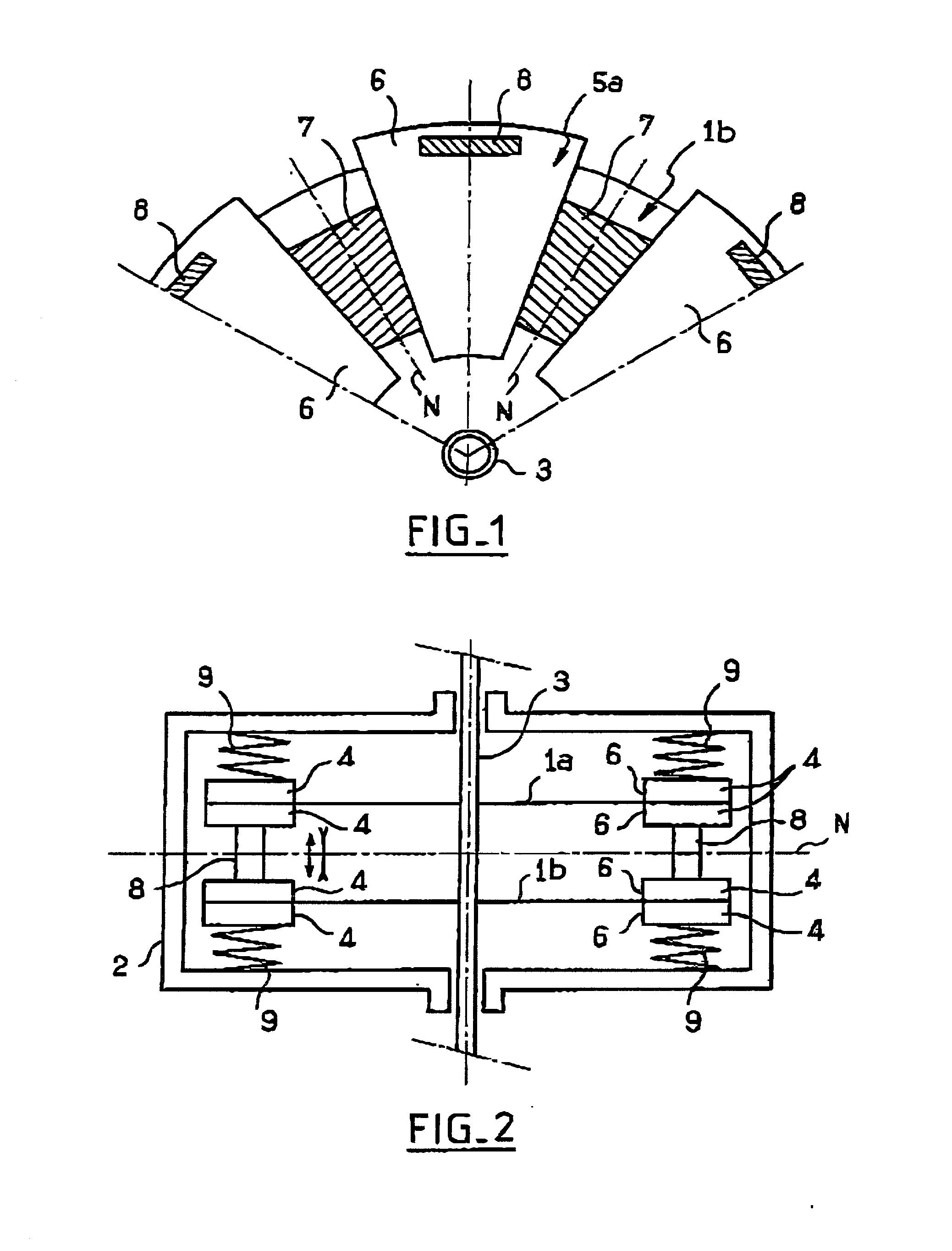
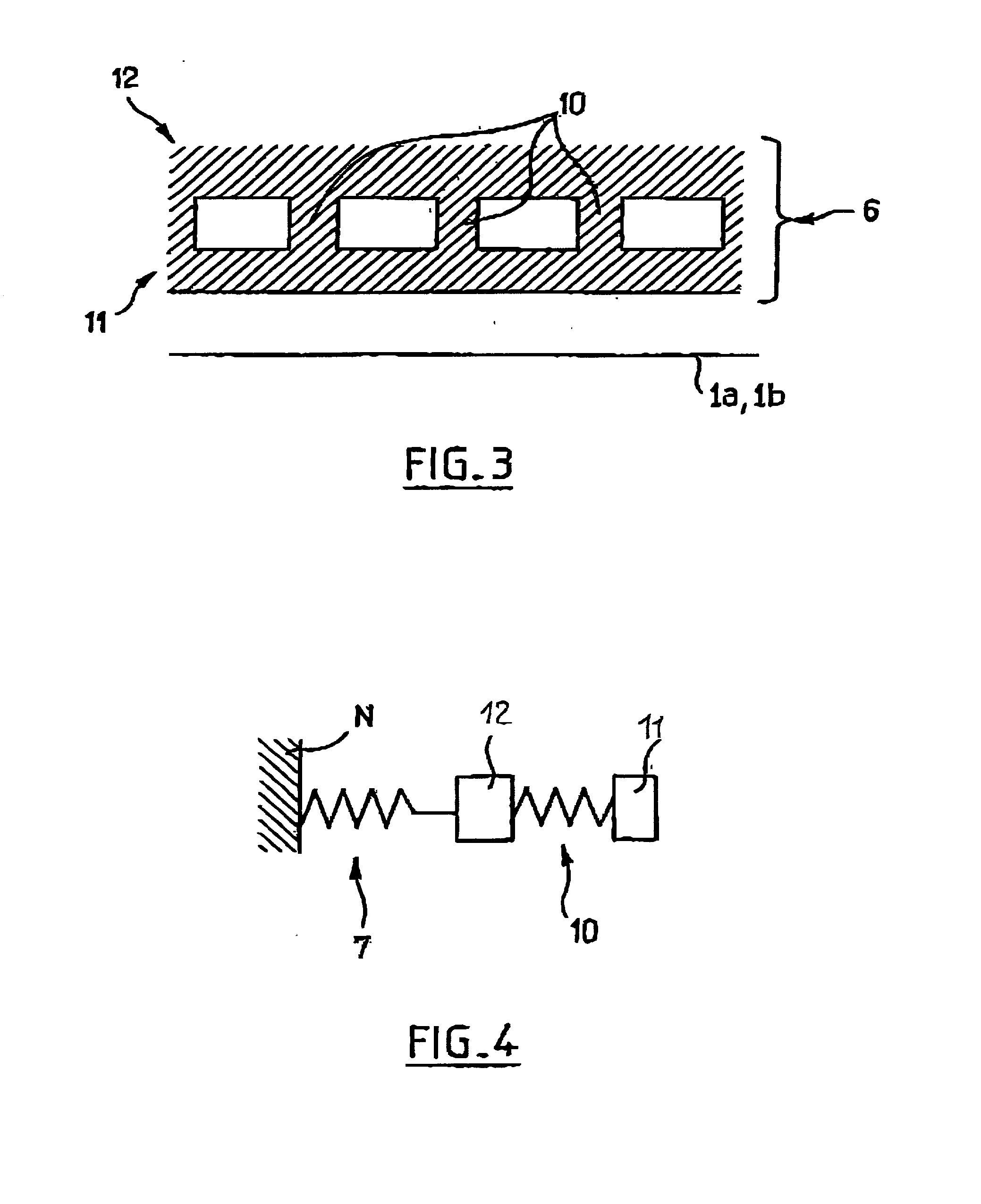
[0049] FIG. 3 shows an example of a possible structure for a petal 6 in a structure of the type shown in FIGS. 1 and 2.

[0050] The petal 6 is constituted by a metal block having a rain portion 12, a contact shoe 11, and an array of intermediate elements 10 interposed between the portion 12 and the contact shoe 11.

[0051] By way of example, the intermediate elements 10 are pegs of cylindrical or other shape, and suitable in particular for accepting bending deformation.

[0052] In a variant, they can be constituted by blades, in particular blades that are generally plane in shape, extending at rest perpendicularly to the general plane of the portion 12 and suitable, in particular, for deforming elastically in bending under the effect of a force that moves the contact shoe 11 relative to the portion 12 parallel to the general plane r...


PUM


Abstract

A vibration motor comprising at least one stationary part and one part driven to move relative to said fixed part, together with excitation means suitable for exerting forces that tend to move rigid contact sectored presented by said fixed part and/or said moving part and to cause said rigid sectors to vibrate in vibration modes that combine tangential vibration and normal vibration, thereby driving the movement of the moving part, said motor presenting for the tangential vibration or the normal vibration a main resonant mode and at least one secondary resonant mode, wherein the secondary resonant mode is at a frequency that is substantially equal to a harmonic frequency of the main resonant mode.

Description

GENERAL FIELD OF THE INVENTION[0001] The present invention relates to vibration motors.[0002] Vibration motors are also known as "ultrasound" motors which refers to their preferred operating frequency, or as "piezoactive" motors which refers to their preferred excitation material.[0003] The invention is particularly advantageous in application to rotary vibration motors, however it can also be applied to linear actuators, the term "vibration motor" in the present specification covering both rotary motors and linear actuators.SUMMARY OF ONE POSSIBLE STRUCTURE FOR A VIBRATION MOTOR[0004] A rotary vibration motor conventionally comprises at least one stator and one rotor, together with execution means for deforming said stator and / or said rotor in vibration modes that combine tangential vibrations and normal vibrations suitable for driving the rotor in continuous rotation.[0005] Particularly advantageous vibration motor structures are proposed in particular in patent applications EP 0 ...

Claims


Application Information

Patent Timeline
IPC IPC(8): H01L41/09H02N2/00
CPCH02N2/02H02N2/10
Inventor AUDREN, JEAN THIERRYBEZANERE, DANIEL
Owner SAGEM DEFENSE SECURITE SA
Why Eureka
Try Eureka