
Droplet generation apparatus

a technology of droplet and generation apparatus, which is applied in the direction of liquid spraying apparatus, movable spraying apparatus, spray nozzle, etc., can solve the problems that the manufacture may not be easily implemented for the control, and achieve the effect of improving the vibration efficiency of the droplet generation apparatus, enhancing the efficiency and accuracy of nubulizing fluid performed by the nozzle disc, and improving the vibration efficiency of the vibratable member

Active Publication Date: 2009-10-27
HEALTH & LIFE CO LTD
View PDF5 Cites 7 Cited by
  • Summary
  • Abstract
  • Description
  • Claims
  • Application Information

AI Technical Summary

Benefits of technology

[0005]A primary object of the present invention is to provide a droplet generation apparatus to improve the droplet generation efficiency.
[0006]To achieve the foregoing object, the droplet generation apparatus of the invention comprises a vibratable member, a connection member, a nozzle disc and a housing. The vibratable member has a first through hole. The nozzle disc has a plurality of apertures facing the first through hole. The connection member is disposed between the vibratable member and the nozzle disc, and has a second through hole corresponding to the first through hole. The housing covers up the vibratable member, the nozzle disc and the connection member. Vibration efficiency generated by the vibratable member then is improved through the connection member.
[0008]Alternatively, the droplet generation apparatus of the invention comprises the vibratable member, the connection member, the nozzle disc, the fastening plate and the housing. The vibratable member has the first through hole. The nozzle disc has a plurality of apertures facing the first through hole. The connection member is disposed between the vibratable member and the nozzle disc, and has a second through hole corresponding to the first through hole. The fastening plate is combined to a plane of the nozzle disc. The housing covers up the vibratable member, the connection member, the nozzle disc and the fastening plate. The vibration efficiency generated by the vibratable member then is improved through the connection member, and an accommodation space is therefore formed by the fastening plate and the nozzle disc.
[0009]Accordingly, vibration efficiency of the droplet generation apparatus is increased by the connection member or the fastening plate or both the connection member and the fastening plate, and by using the housing as an o-shaped ring. The efficiency and accuracy of nubulizing fluid performed by the nozzle disc then is enhanced without controlling the interval.

Problems solved by technology

The manufacture may not be easily implemented for the control.

Method used


Image

  • Droplet generation apparatus
  • Droplet generation apparatus
  • Droplet generation apparatus

Examples


Embodiment Construction

[0019]Referring to the related figures for the droplet generation apparatus according to a preferred embodiment of the present invention, wherein the same elements are described by the same reference numerals.

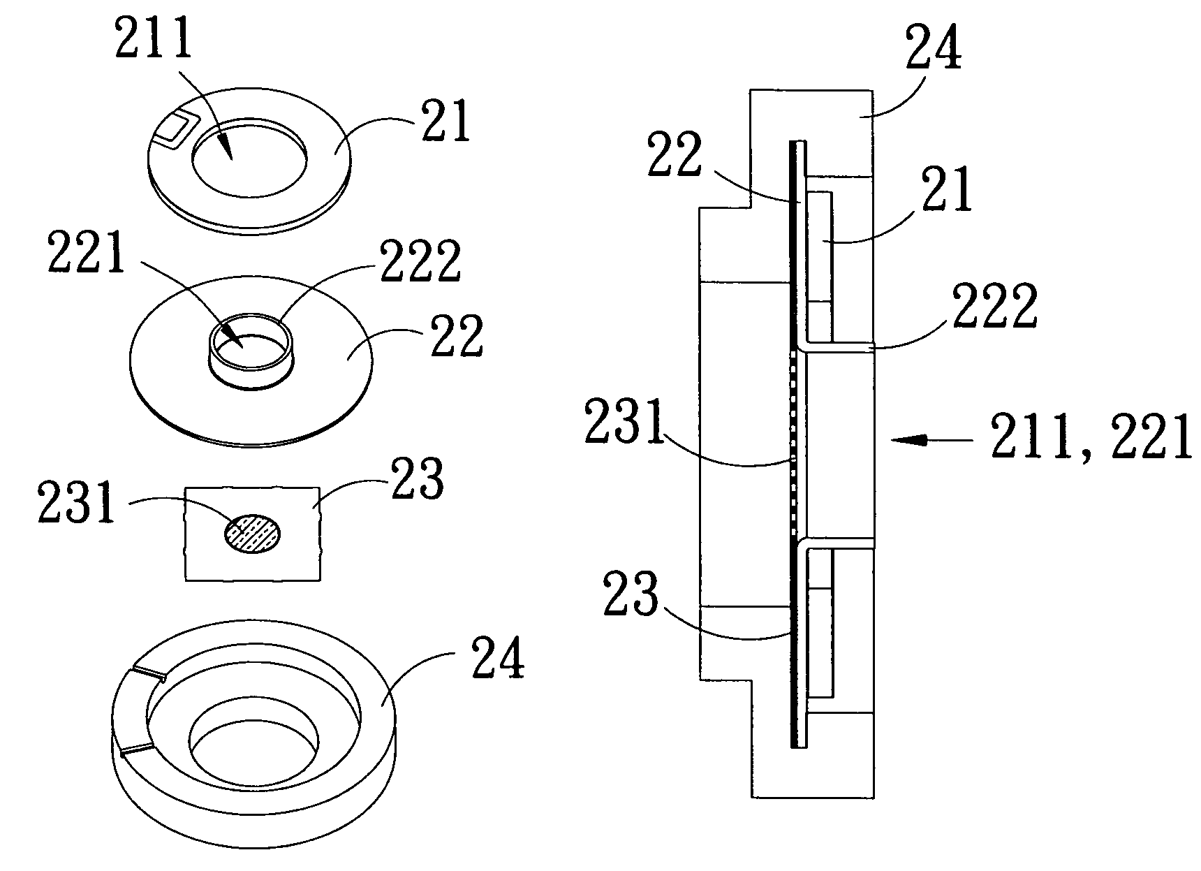
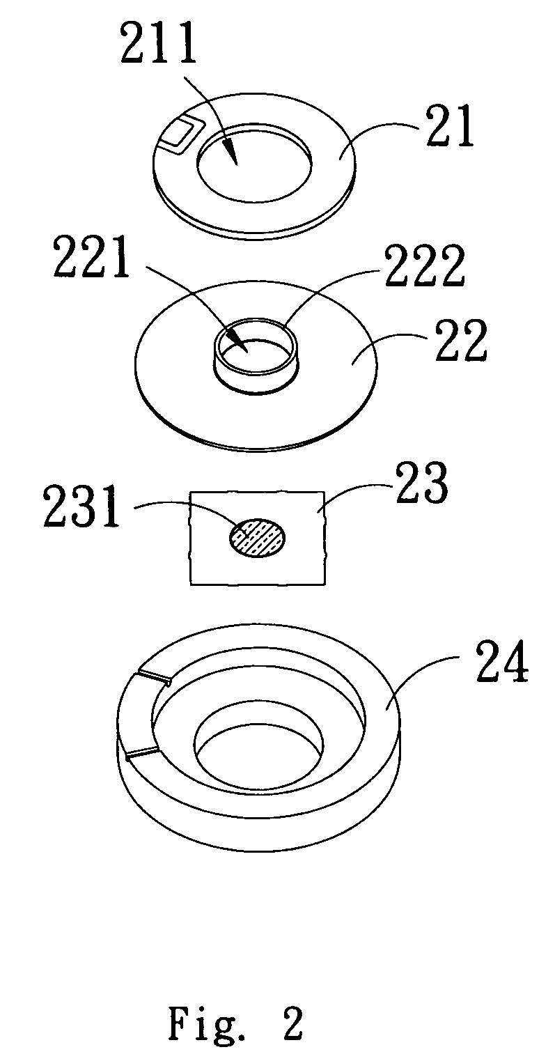
[0020]Referring to FIG. 2 to FIG. 3, FIG. 2 is an exploded assembly drawing illustrating a droplet generation apparatus of the invention, and FIG. 3 is an assembly cross-section view illustrating a droplet generation apparatus. As shown in FIG. 2, the droplet generation apparatus 2 is applied to an atomizer, and comprises a vibratable member 21, a connection member 22, a nozzle disc 23 and a housing 24. The vibratable member 21 has a first through hole 211, and the nozzle disc 23 has a plurality of apertures 231 facing the first through hole 211. The connection member 22 is disposed between the vibratable member 21 and the nozzle disc 23, and has a second through hole 221 corresponding to the first through hole 211, and is combined with the vibratable member 21 and the nozzle d...


PUM


Abstract

A droplet generation apparatus is applied to a nebulizer. The droplet generation apparatus comprises a vibratable member, a nozzle disc, a housing and a connection member or a fastening plate or both the connection member and the fastening plate. The vibratable member has a first through hole. The nozzle disc has a plurality of apertures facing the first through hole, and is combined with the vibratable member. The connection member is disposed between the vibratable member and the nozzle disc, and has a second through hole corresponding to the first through hole. Alternatively, the fastening plate is combined with the nozzle disc. The housing covers up the combination of the vibratable member, the nozzle disc and the connection member or the fastening plate. Vibration efficiency generated by the vibratable member is improved through the connection member. An accommodation space is formed by the fastening plate and the nozzle disc.

Description

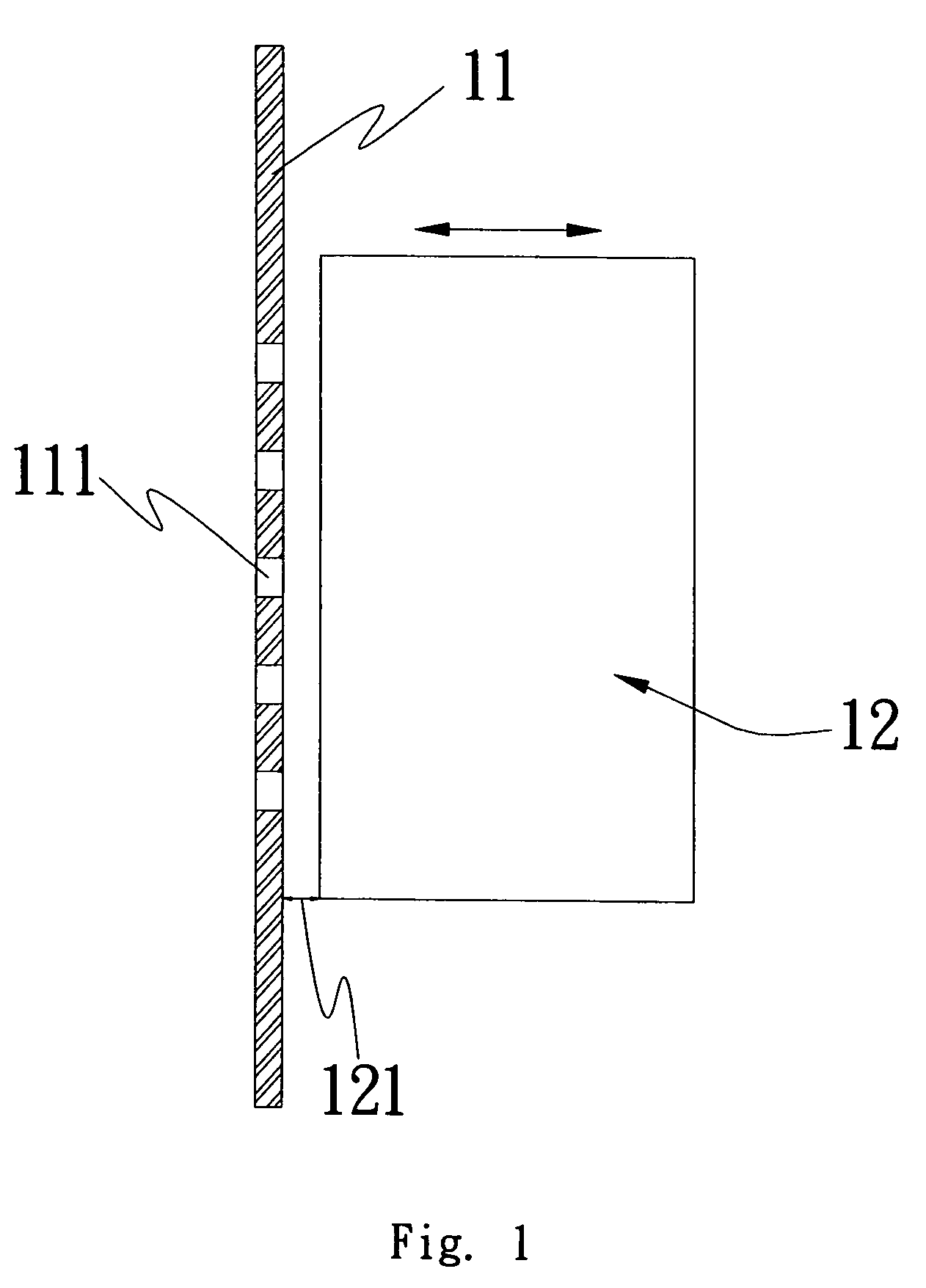
FIELD OF THE INVENTION[0001]The present invention generally relates to a droplet generation apparatus, and more specifically relates to the droplet generation apparatus that improves the droplet generation efficiency.BACKGROUND OF THE INVENTION[0002]An atomizer used in the current market is usually composed of a vibratable element made by a piezoelectric material and a nozzle disc, wherein the vibratable element is disposed in a chamber which is used to accommodate liquid, or connected to the nozzle disc. High speed reciprocating motion then is generated when the piezoelectric material is conducted electricity so that liquid can pass through the nozzle disc. Alternatively, the nozzle disc is driven to generate vibration so that liquid then is squeezed to be sprayed from the nozzle disc. Moreover, liquid is sprayed from micro-apertures of the nozzle disc to become micro droplets to achieve the goal of nebulizing liquid.[0003]Referring to FIG. 1 for the assembly cross-section drawing ...

Claims


Application Information

Patent Timeline
Patent Type & Authority Patents(United States)
IPC IPC(8): B05B1/08
CPCB05B17/0646
Inventor YU, SHAN-YILIU, HAN-CHANGTSAI, WEN-YU
Owner HEALTH & LIFE CO LTD
Learn More