
High-efficiency hot melting riveting device for lithium ion power battery pack

A power battery pack and hot-melt riveting technology, which is applied to household appliances, other household appliances, household components, etc., can solve the problem of inability to meet the strength requirements of the power battery pack and the plastic structure, the hot-melt wrapping force is small, and the hot-melt surface Problems such as wire drawing can reduce maintenance time, solve hot melt deformation, and save costs.

Active Publication Date: 2021-10-08
SINOWATT DONGGUAN
View PDF9 Cites 5 Cited by
  • Summary
  • Abstract
  • Description
  • Claims
  • Application Information

AI Technical Summary

Problems solved by technology

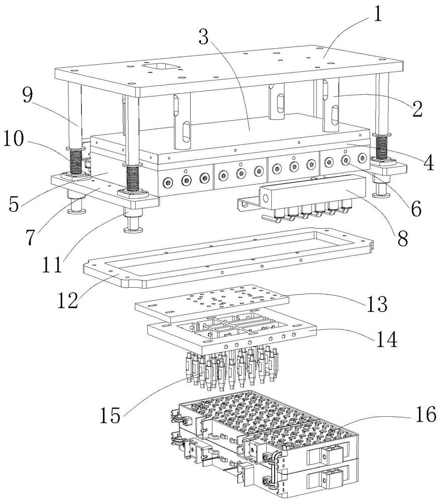
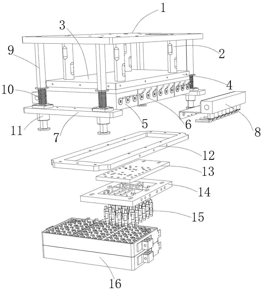
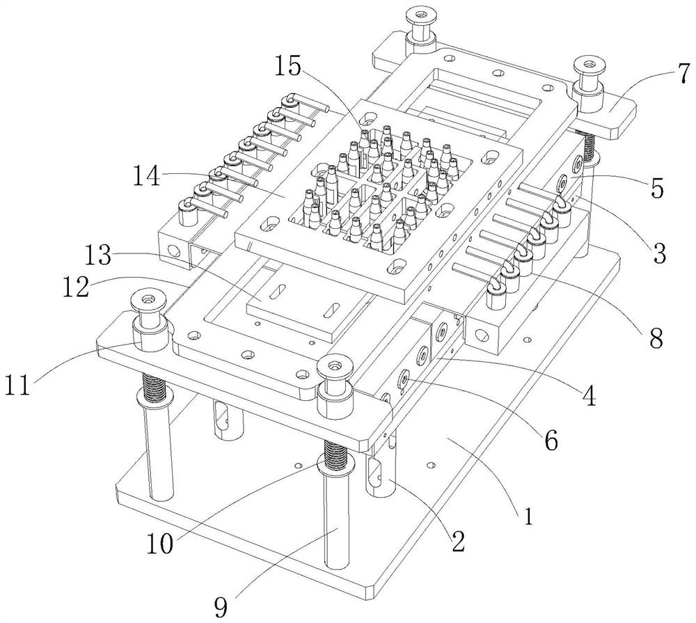
[0004] The purpose of the present invention is to provide a high-efficiency hot-melt riveting device for lithium-ion power battery packs, which can realize temperature control, graded preheating, heating, baking and cooling through the set grading preheating hot-melt mechanism, so that it can be graded during hot-melt riveting Preheating the plastic hot-melt column and quickly lowering the temperature of each hot-melt point to solidify the plastic prevents the plastic hot-melt column from being directly separated from the hot-melt head when it is in a semi-molten state. In the semi-melted high-temperature state, when it is separated from the hot-melt head, it will cause the hot-melt surface to be drawn, deformed, and burnt badly, and the hot-melt wrapping force is very small, which cannot meet the power battery pack manifold and plastic fixing used in vibration conditions. The problem of structural strength requirements

Method used


Image

  • High-efficiency hot melting riveting device for lithium ion power battery pack
  • High-efficiency hot melting riveting device for lithium ion power battery pack
  • High-efficiency hot melting riveting device for lithium ion power battery pack

Examples


Embodiment Construction

[0024] In order to make the objectives, technical solutions and advantages of the present invention, the present invention will be described in further detail below with reference to the accompanying drawings and examples. It should be understood that the specific embodiments described herein are merely intended to illustrate the invention and are not intended to limit the invention.

[0025] The implementation of the present invention will be described in detail below with reference to the specific embodiments.

[0026] The same or similar components in the drawings of the present embodiment correspond to the same or similar components; in the description of the present invention, it is to be understood that if there is a term "upper", "lower", "left", "right", etc. The orientation or positional relationship indicated is based on the orientation or positional relationship shown in the drawings, is merely intended to describe the present invention and simplified description, rathe...


PUM

PropertyMeasurementUnit
diameteraaaaaaaaaa

Abstract

The invention relates to the technical field of battery hot melting connection, and discloses a high-efficiency hot melting riveting device for a lithium ion power battery pack. The device comprises an upper mold plate, wherein guide columns are arranged on the four sides of the bottom end of the upper mold plate, springs are arranged on the outer walls of the guide columns, the lower portions of the springs are fixed to a push plate fixing seat, the guide columns penetrate through the push plate fixing seat and extends to the lower portion, a lower mold plate is arranged below the middle of the upper mold plate, a graded preheating hot melting mechanism is arranged at the bottom end of the lower mold plate, and the two sides of the graded preheating hot melting mechanism extend to the bottom end of the push plate fixing seat. According to the device, temperature control, graded preheating, heating baking and active heat dissipation cooling are achieved through the arranged graded preheating hot melting mechanism, in this way, during hot melting riveting forming, the temperature of all hot melting points can be rapidly reduced so that plastic can be solidified, it is avoided that a plastic hot melting column in a semi-melting state is directly separated from a hot melting head, and the problems of deformation of the hot melting point, strain, insufficiency, no wrapping force and insufficient riveting strength are solved.

Description

Technical field [0001] The present invention relates to the technical field of battery thermal fusion connection, and in particular, it relates to a highly efficient hot-fuser riveting device for a lithium ion power battery. Background technique [0002] Small home appliances, toy products generally apply plastic riveting process to fix some static use of small buttons, PCB boards, and most of them are hot melt rivets of single hot melt or less than 10 points. [0003] The hot melt device is heated, and the plastic hot melting column is continuously held in a high temperature. When the hot melt is completed, the plastic is still in a half-melted high temperature state, which causes hot melt surface when separated from the plastic hot melt column. Deformation, poor burning, and hot melt packaging force is small, and cannot meet the power battery assembly of the vibration conditions and the structural strength requirements of the plastic fixed structure. Inventive content [0004]...

Claims


Application Information

Patent Timeline
Patent Type & Authority Applications(China)
IPC IPC(8): B29C65/60B29C65/18B29L31/34
CPCB29C65/601B29C65/18B29C66/0342B29L2031/3468Y02E60/10
Inventor 罗辉姚纪全吴国强万里鹏徐鲲郭密曾素琼兰水静仇爽
Owner SINOWATT DONGGUAN
Learn More