Liftable projector using new-generation information technology

An information technology and projector technology, applied in the field of projectors, can solve the problems of reducing the effect, not being able to greatly adjust the projection height of the projector, inconvenience, etc., and achieve the effect of greatly adjusting the projection height and facilitating the adjustment of the projection height

Inactive Publication Date: 2021-10-08
黄春香
View PDF0 Cites 2 Cited by
  • Summary
  • Abstract
  • Description
  • Claims
  • Application Information

AI Technical Summary

Problems solved by technology

[0002] A projector, also known as a projector, is a device that can project images or videos onto a screen, and can be connected to a computer, VCD, DVD, BD, game console, DV, etc. through different interfaces to play the corresponding video signal; Projectors are widely used in homes, offices, schools and entertainment venues. At present, projectors are generally placed on desktops, or installed on ceilings and walls. It is very inconvenient to adjust the height of projector projection, and The height of the projector projection cannot be greatly adjusted, which will reduce the effect of people's viewing experience

Method used


Image

  • Liftable projector using new-generation information technology
  • Liftable projector using new-generation information technology
  • Liftable projector using new-generation information technology

Examples


Embodiment 1

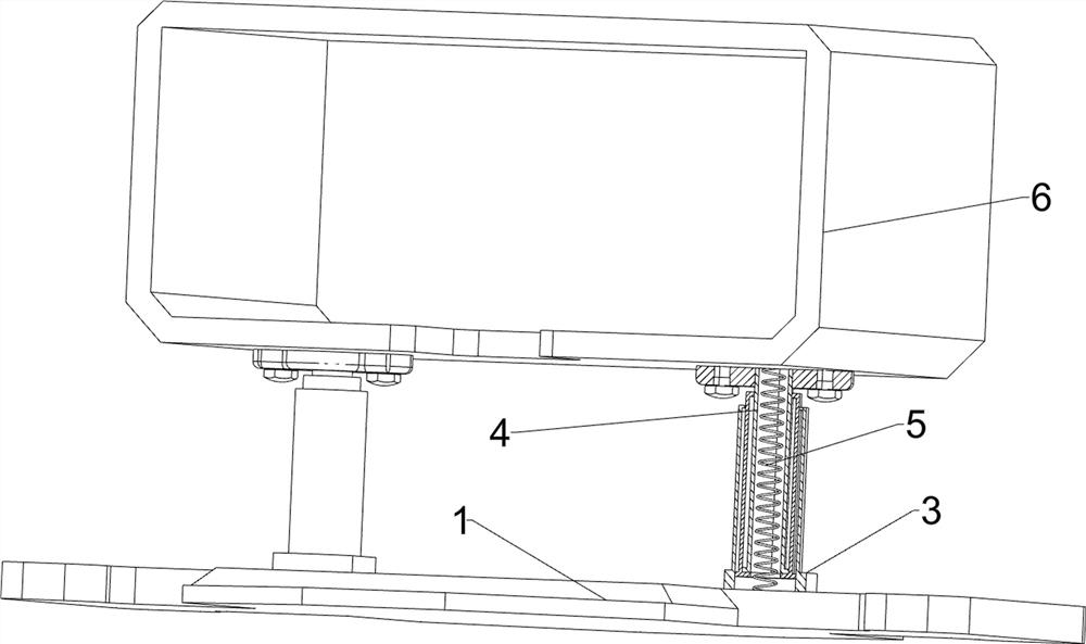
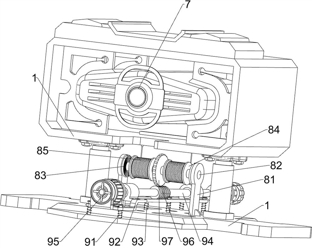
[0028] A liftable projector using a new generation of information technology, such as Figure 1-3 As shown, it includes a mounting plate 1, a connecting block 2, a connecting cylinder 3, a telescopic cylinder 4, a compression spring 5, a mounting frame 6, a projector 7, a wire assembly 8 and a rotating assembly 9, and the four outer sides of the mounting plate 1 Connecting blocks 2 are connected at the corners, two connecting cylinders 3 are symmetrically connected on the top of the mounting plate 1, and a telescopic cylinder 4 is slidably connected in the connecting cylinder 3, and an installation frame 6 is connected between the tops of the two telescopic cylinders 4. A compression spring 5 is connected between the installation frame 6 and the connecting cylinder 3, a projector 7 is placed in the installation frame 6, and a pay-off assembly 8 and a rotation assembly 9 are respectively installed on the top of the installation plate 1, and the rotation assembly 9 and the releas...

Embodiment 2

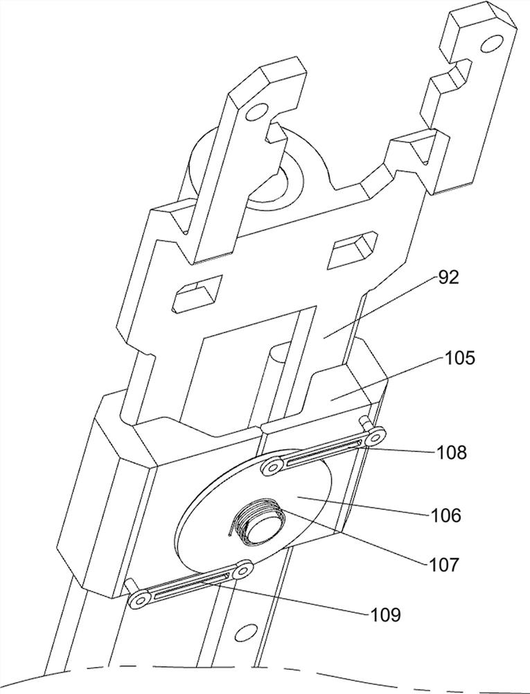
[0033] On the basis of Example 1, such as figure 1 , Figure 4 , Figure 5 and Image 6 As shown, a fixing assembly 10 is also included, and the fixing assembly 10 includes a first sliding frame 102, a clamping plate 103, a return spring 104, a wedge block 105, a wheel disc 106, a first torsion spring 107, a first connecting rod 108 and a first connecting rod 108. Two connecting rods 109, four chutes 101 are symmetrically arranged on the top of the mounting plate 1, and the first sliding frame 102 is slidably connected in the chute 101, and the top of the first sliding frame 102 is connected with a clamping plate 103, and the clamping plate 103 and the sliding The plate 92 cooperates, two return springs 104 are connected between the first sliding frame 102 and the mounting plate 1, the wedge-shaped block 105 is connected to the inner surface of the clamping plate 103, the wedge-shaped block 105 cooperates with the sliding plate 92, and the top of the mounting plate 1 is symmet...

Embodiment 3

[0036] On the basis of Example 2, such as figure 1 , Figure 4 and Figure 5 As shown, a buffer assembly 11 is also included. The buffer assembly 11 includes a second fixed plate 111, a second sliding frame 112, a buffer spring 113 and a supporting plate 114. The left front side and the right rear side of the top of the installation plate 1 are connected with a second The fixed plate 111, the second fixed plate 111 is slidably connected with the second sliding frame 112, and there are two buffer springs 113 symmetrically connected between the second sliding frame 112 and the second fixed plate 111. A supporting plate 114 is connected, and the supporting plate 114 cooperates with the installation frame 6 .

[0037] When the mounting frame 6 moves down quickly, the mounting frame 6 can be supported by the supporting plate 114, thereby through the cooperation of the second sliding frame 112, the buffer spring 113 and the supporting plate 114, the mounting frame 6 can be damped,...


PUM


Abstract

The invention discloses a liftable projector using a new-generation information technology. The liftable projector using the new-generation information technology comprises an installation plate, connecting cylinders, a projector body, a pay-off assembly and a rotating assembly, wherein a plurality of connecting blocks are connected to the outer side surface of the installation plate; the two connecting cylinders are connected to the end of the installation plate, telescopic cylinders are slidably connected into the connecting cylinders, an installation frame is connected between the end parts of the telescopic cylinders, and compression springs are connected between the installation frame and the connecting cylinders; the projector body is arranged in the installation frame; the pay-off assembly is installed at the end part of the installation plate; and the rotating assembly is installed at the end part of the installation plate, and in transmission connection with the pay-off assembly. According to the invention, the pay-off assembly can be driven to work through the rotating assembly, the height of the projector can be conveniently adjusted through the pay-off assembly, the height of the projector can be greatly adjusted, and therefore the purposes that the projection height can be conveniently adjusted, and the projection height can be greatly adjusted are realized.

Description

technical field [0001] The invention relates to a projector, in particular to a projector that can be raised and lowered by using a new generation of information technology. Background technique [0002] A projector, also known as a projector, is a device that can project images or videos onto a screen, and can be connected to a computer, VCD, DVD, BD, game console, DV, etc. through different interfaces to play the corresponding video signal; Projectors are widely used in homes, offices, schools and entertainment venues. At present, projectors are generally placed on desktops, or installed on ceilings and walls. It is very inconvenient to adjust the height of projector projection, and The height of the projection of the projector cannot be greatly adjusted, which will reduce the effect of people's viewing experience. Contents of the invention [0003] The object of the present invention is to provide a new-generation information technology liftable projector, which can ea...

Claims


Application Information

Patent Timeline
Patent Type & Authority Applications(China)
IPC IPC(8): F16M11/20F16M11/24F16M11/26F16M13/02G03B21/54F16F15/04F16F15/067
CPCF16M11/20F16M11/24F16M11/26F16M13/02G03B21/54F16F15/04F16F15/067
Inventor 黄春香
Owner 黄春香
Why Eureka
Try Eureka