A distributed power generation system connected to a traction substation and its control method

A traction substation and distributed power generation technology, applied in electrical components, circuit devices, AC network circuits, etc., to reduce wind curtailment, improve power utilization, and improve utilization efficiency.

Active Publication Date: 2021-11-30
SOUTHWEST JIAOTONG UNIV
View PDF3 Cites 0 Cited by
  • Summary
  • Abstract
  • Description
  • Claims
  • Application Information

AI Technical Summary

Problems solved by technology

[0006] The purpose of the present invention is to provide a distributed power generation system connected to the traction substation, which can effectively solve the technical problem of connecting the distributed new energy power generation device to the traction power supply system

Method used


Image

  • A distributed power generation system connected to a traction substation and its control method
  • A distributed power generation system connected to a traction substation and its control method
  • A distributed power generation system connected to a traction substation and its control method

Examples


Embodiment 1

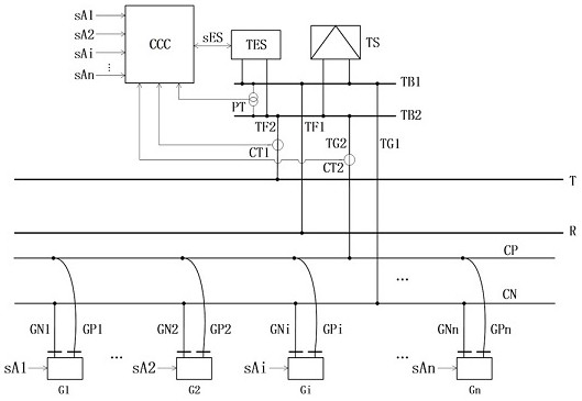
[0041] Such as figure 1 As shown, this embodiment provides a distributed power generation system connected to a traction substation, including a traction substation TS and a traction network. The traction side of the traction substation TS is connected to the traction bus TB1 and the traction bus TB2 respectively. The traction bus TB1 is connected to the R line of the traction network through the feeder TF1, and the traction bus TB2 is connected to the T line of the traction network through the feeder TF2. CT1, power cable CP line and power cable CN line are laid in parallel along the railway, and n new energy power generation devices are installed along the power cable CP line, which are specifically recorded as new energy power generation device G1, new energy power generation device G2, new energy power generation device Gi, ..., new energy power generation device Gn;

[0042] The traction substation TS is equipped with a central coordinating controller CCC, and the measur...

Embodiment 2

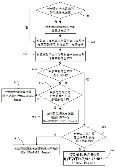
[0054] Such as image 3 As shown, this embodiment provides a control method based on the distributed power generation system connected to the traction substation provided in Embodiment 1, which is applied to the central coordination controller CCC and realized through the following technical solutions, specifically involving the following steps:

[0055] Step S1: The central coordinating controller CCC judges whether there is a faulty new energy power generation device, and if so, controls the faulty new energy power generation device to stop running;

[0056] Step S2: The central coordinating controller CCC controls the new energy power generation device under normal working conditions to run independently.

[0057] Preferably, as image 3 As shown, the central coordinating controller CCC controls the new energy power generation device under normal working conditions to operate independently, that is, step S2 includes:

[0058] Step S21: the central coordinating controller ...


PUM


Abstract

The invention provides a distributed power generation system connected to a traction substation and a control method, and belongs to the technical field of electrified railway traction power supply. The traction side of the same-phase traction substation is connected to the traction busbar, and the traction busbar is connected to the traction network through the feeder line. The new energy power generation device is connected to the traction busbar of the traction substation through the power cable in the corridor along the railway line, and the traction station is equipped with central coordination control The device monitors the power of the traction network in real time, dynamically controls the output power of the new energy power generation device, and realizes the optimal utilization of new energy power. It is mainly used for power dispatching and management of distributed power generation system connected to traction substation.

Description

technical field [0001] The invention relates to the technical field of AC electrified railway power supply, in particular to a distributed power generation system connected to a traction substation and a control method. Background technique [0002] There have been a large number of successful application cases of new energy and renewable energy power generation in the power system, and the railway system has also been explored. Promote and apply new energy and renewable energy power generation along the railway line according to the principles of adapting measures to local conditions and multi-energy complementarity. [0003] Chinese application number 202110028103.9 discloses "A Grid-connected System and Control Method for In-phase Traction Power Supply and Off-site Power Generation", but this application only considers single-point off-site power generation, and does not consider the linear distribution of railway lines and the coexistence of multiple power generation sys...

Claims


Application Information

Patent Timeline
Patent Type & Authority Patents(China)
IPC IPC(8): H02J3/46H02J3/28H02J3/32H02J13/00
CPCH02J3/381H02J3/466H02J3/28H02J3/32H02J13/00017H02J2300/20H02J2300/22H02J2300/28H02J2300/30H02J2300/40Y02E70/30
Inventor 黄小红李群湛吴波
Owner SOUTHWEST JIAOTONG UNIV
Why Eureka
Try Eureka